
External power pipe rod conveyor

A conveyor and power pipe technology, applied in the field of external power pipe-rod conveyors, can solve the problems of low efficiency, high labor intensity, and inconvenient use in areas where electricity is not applicable.

Pending Publication Date: 2021-02-26
山东泽元石油机械有限公司
View PDF0 Cites 0 Cited by
  • Summary
  • Abstract
  • Description
  • Claims
  • Application Information

AI Technical Summary

Problems solved by technology

[0002] With the development of technology, the operating equipment and technology of oil wells in oilfields are also constantly improving. In the traditional oilfield minor repair operations, most of the lifting and lowering pipe rods are manually pulled out. This traditional operation method is labor-intensive and low-efficiency. , many security risks
At present, the external power pipe and rod conveyors used in major oilfields for minor repair work use high-power motors as the power source to work, but for some water wells or places where electricity is far away and other places where electricity is inconvenient, external power pipe and rod conveyors cannot be used. Power pipe rod conveyor
Therefore, how to solve the problem in the prior art that the external power pipe rod conveyor needs to be driven by electricity and is not suitable for use in areas where electricity is inconvenient is a technical problem that those skilled in the art need to solve urgently

Method used


Image

  • External power pipe rod conveyor
  • External power pipe rod conveyor
  • External power pipe rod conveyor

Examples


Embodiment Construction

[0028] In order to make the purpose, technical solution and advantages of the present invention clearer, the technical solution of the present invention will be described in detail below. Apparently, the described embodiments are only some of the embodiments of the present invention, but not all of them. Based on the embodiments of the present invention, all other implementations obtained by persons of ordinary skill in the art without making creative efforts fall within the protection scope of the present invention.

[0029] Hereinafter, the embodiments will be described in detail in conjunction with the accompanying drawings. In addition, the examples shown below do not limit the content of the invention described in the claims in any way. In addition, all the contents of the configurations shown in the following embodiments are not limited to be essential to the solutions of the invention described in the claims.

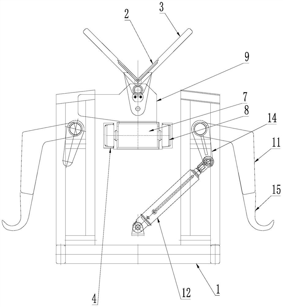
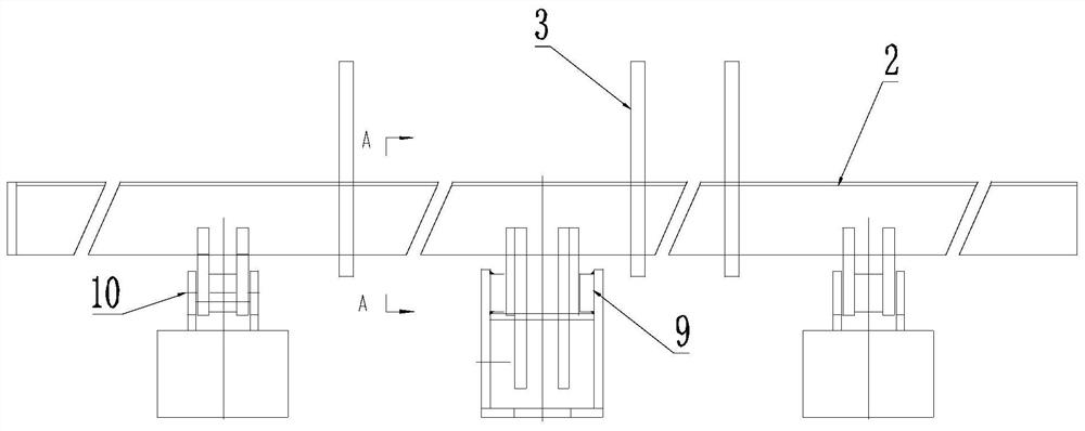
[0030] refer to Figure 1-7 As shown, an external power ...


PUM


Abstract

The invention provides an external power pipe rod conveyor, and relates to the technical field of oil field workover devices. The external power pipe rod conveyor comprises a rack, a hoisting mechanism, a telescopic mechanism, a turnover mechanism and a hydraulic system, wherein at least one side of the rack is provided with a feeding mechanism; the hoisting mechanism is arranged on the rack; thetelescopic mechanism is arranged on the hoisting mechanism; the turnover mechanism is arranged on the telescopic mechanism, the telescopic mechanism is used for driving the turnover mechanism to move,and the turnover mechanism is used for turning over towards one side of the rack; and the hydraulic system comprises a hydraulic quick coupling used for communicating with a hydraulic loop of an external hydraulic source, a flow control system used for controlling the flow of hydraulic oil in the hydraulic system, a high-pressure filter used for filtering the hydraulic oil in the hydraulic systemand a hydraulic valve set used for controlling all the mechanisms to act. Due to the arrangement, the external power pipe rod conveyor can be used in a well site with an electric hydraulic pump station, can also be used in a well site with a vehicle-mounted hydraulic power source when the electric hydraulic pump station cannot be powered on, and can meet the use requirements of any well site.

Description

technical field [0001] The invention relates to the technical field of oil field workover devices, and more specifically relates to an external power pipe and rod conveyor. Background technique [0002] With the development of technology, the operating equipment and technology of oil wells in oilfields are also constantly improving. In the traditional oilfield minor repair operations, most of the lifting and lowering pipe rods are manually pulled out. This traditional operation method is labor-intensive and low-efficiency. , many security risks. At present, the external power pipe and rod conveyors used in major oilfields for minor repair work use high-power motors as the power source to work, but for some water wells or places where electricity is far away and other places where electricity is inconvenient, external power pipe and rod conveyors cannot be used. Set the power tube rod conveyor. Therefore, how to solve the problem in the prior art that the external power pip...

Claims


Application Information

Patent Timeline
IPC IPC(8): E21B19/14E21B19/15
CPCE21B19/14E21B19/155
Inventor 巩亚明
Owner 山东泽元石油机械有限公司
Learn More