Parallel grid simulation method for aero-engine combustion chamber through-flow model

A technology of aero-engine and simulation methods, applied in design optimization/simulation, computer-aided design, CAD numerical modeling, etc., can solve problems such as incomplete flow drawing depiction

Active Publication Date: 2021-02-26
BEIHANG UNIV
View PDF3 Cites 6 Cited by
  • Summary
  • Abstract
  • Description
  • Claims
  • Application Information

AI Technical Summary

Problems solved by technology

However, the missing geometry of the intake funnel results in an incomplete picture of the flow inside the combustion chamber

Method used


Image

  • Parallel grid simulation method for aero-engine combustion chamber through-flow model
  • Parallel grid simulation method for aero-engine combustion chamber through-flow model
  • Parallel grid simulation method for aero-engine combustion chamber through-flow model

Examples


example

[0181] Example description:

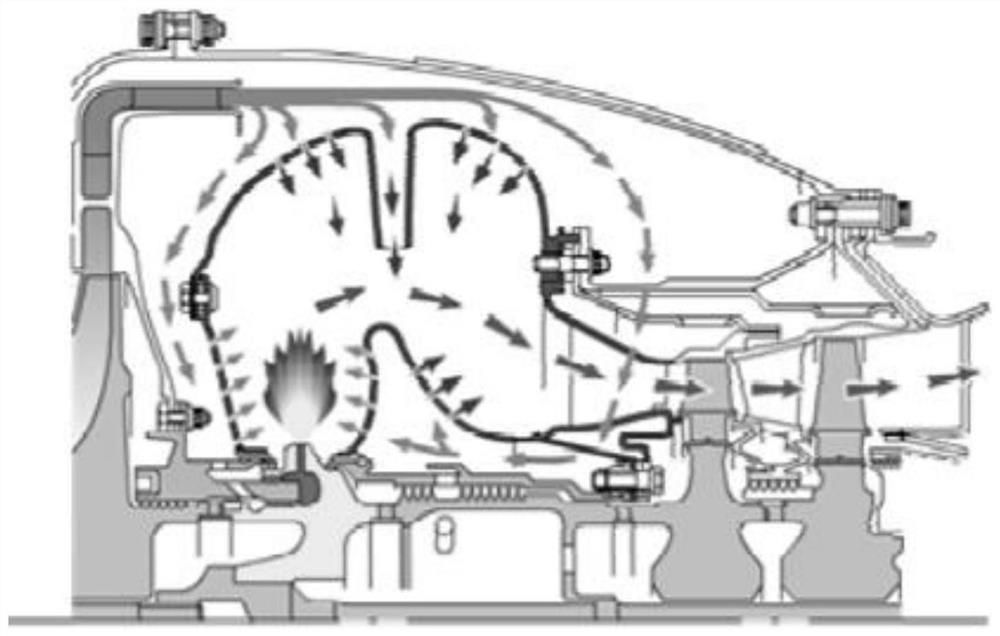
[0182] Based on the throughflow analysis software developed by our research group, combined with the parallel grid method of the combustion chamber intake bucket in the aeroengine throughflow model proposed by the present invention, the simulation fidelity of the combustion chamber intake bucket in the throughflow simulation software is preliminarily explored Effects on the flow field for throughflow calculations. Finally, the effectiveness of the present invention is verified by comparative analysis with the results of three-dimensional numerical simulation, experimental data, and flow calculation results obtained by Ivanov et al. by simplifying the intake funnel into large holes.

[0183] The first step, flow field numerical simulation

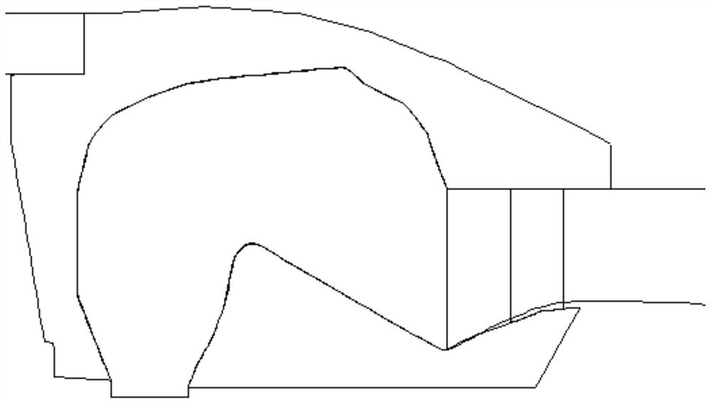
[0184] The verification object adopted in this example is the baffle annular combustor adopted by a small turbojet engine, and its section view and meridian view are respectively as follows Figure 10 and Fi...


PUM

PropertyMeasurementUnit
Widthaaaaaaaaaa

Abstract

The invention provides a parallel grid simulation method for an aero-engine combustion chamber through-flow mode, complete depiction of a geometric structure of a combustion chamber air inlet bucket in through-flow calculation can be realized and fidelity of numerical simulation of an aero-engine combustion chamber is ensured. For a meridian plane where the combustion chamber air inlet hopper is located, the meridian plane corresponds to the inner space and the outer space of the air inlet hopper. The flow structures in the two spaces are completely different, and the same solving mode cannotbe adopted. Therefore, firstly, a control equation of through-flow calculation is obtained through derivation, and through-flow items which need to be processed independently and are caused by the special structure of the combustion chamber air inlet hopper are clarified. Secondly, the internal flux and the external flux of the air inlet hopper are calculated by utilizing a parallel grid method, and further completing the depiction of the internal and external gas flow of the air inlet hopper and the mixing physical process of the air inlet hopper in the through-flow model. The method has certain guiding significance and engineering practical value for improving the precision of the through-flow model for numerical simulation of the combustion chamber of the gas turbine.

Description

technical field [0001] The invention relates to a parallel grid simulation method of an air intake bucket in a through-flow model of an aero-engine combustion chamber, which relates to aerodynamics and numerical simulation of an aero-engine combustion chamber, and belongs to the field of aerodynamic design and analysis of an aero-engine combustion chamber. Background technique [0002] Aeroengines have been used as the main power plant of aero-vehicles since their advent in the 1940s. In recent decades, the performance of aero-engines has been continuously improved, occupying an important position in both military and civilian fields. At present, the main fighters in active service in various developed countries are third-generation fighters, and their engines have a thrust-to-weight ratio of about 8, such as F100, F110, AL-31Ф, etc.; in recent years, engines with a thrust-to-weight ratio of about 10 (F119 , EJ200, AЛ-41Ф, etc.) The fourth-generation fighter jets have also ...

Claims


Application Information

Patent Timeline
IPC IPC(8): G06F30/15G06F30/28G06F30/23G06F111/10G06F119/14G06F119/08
CPCG06F30/15G06F30/28G06F30/23G06F2111/10G06F2119/14G06F2119/08
Inventor 金东海桂幸民刘晓恒
Owner BEIHANG UNIV
Why Eureka
Try Eureka