Dye processing equipment for cloth pretreatment dyeing process

A pretreatment dyeing and dye processing technology, which is applied in the direction of mixed material pretreatment, chemical/physical process, filtering and screening, etc., can solve the problems that cannot be eliminated in time, affect material screening, and multi-impurity waste, so as to reduce material transfer and speed up Filter, improve the effect of the filter effect

Inactive Publication Date: 2021-03-02
安徽子延科技有限公司
View PDF0 Cites 0 Cited by
  • Summary
  • Abstract
  • Description
  • Claims
  • Application Information

AI Technical Summary

Problems solved by technology

[0008] However, every time the screening is completed, the materials need to be collected again and then transferred. Therefore, the operation between material screening and mixing is inconvenient. A lot of impurities and waste, etc., cannot be eliminated in time, which will affect the subsequent material screening

Method used


Image

  • Dye processing equipment for cloth pretreatment dyeing process
  • Dye processing equipment for cloth pretreatment dyeing process
  • Dye processing equipment for cloth pretreatment dyeing process

Examples


Embodiment 1

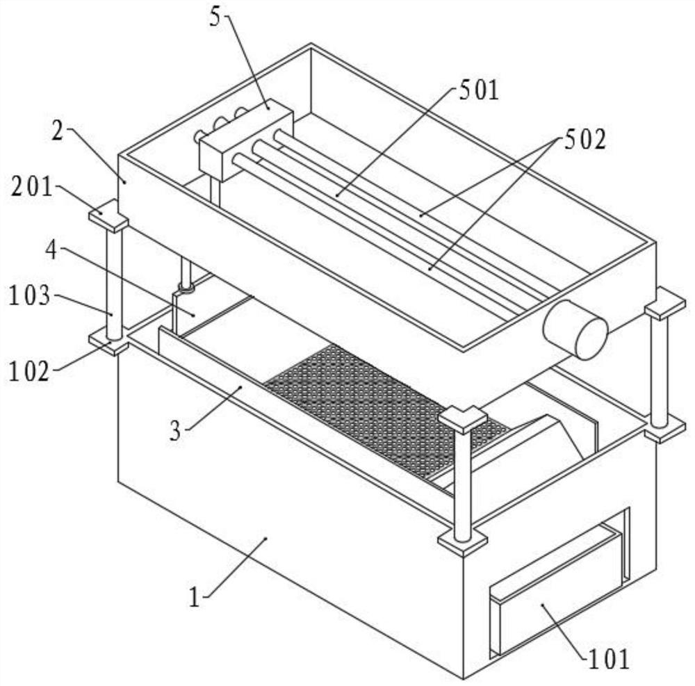
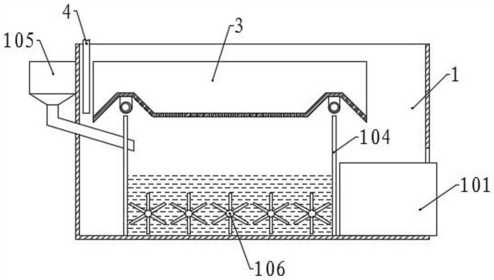
[0048] Please refer to the accompanying drawings, the present invention provides a technical solution: a kind of dye processing equipment for fabric pre-treatment dyeing process, comprising a mixing box 1, the bottom surface of the mixing box 1 is symmetrically fixed with two vertical partitions 104, two partitions A mixing tank is set between the plates 104, and a stirring assembly is arranged in the mixing tank. A notch is arranged at the bottom of the right wall of the mixing box 1, and a collection box 101 is slidably connected to the outlet, and the collection box 101 extends into the right side of the mixing box 1. side lumen;

[0049] A rectangular frame 2 is correspondingly fixed above the mixing tank, and a moving component is arranged in the rectangular frame 2, and a scraping component is connected to the bottom of the moving component, and a screening tank 3 is correspondingly provided in the mixing tank, and the scraping component extends into the screening tank 3 ...

Embodiment 2

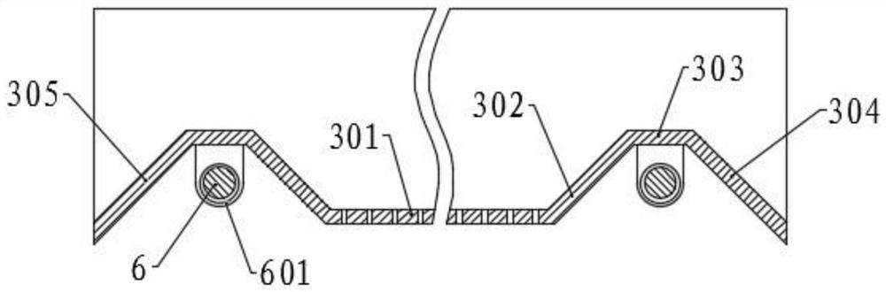
[0063] The structure of this embodiment is basically the same as that of Embodiment 1, the difference is that the limit shafts 404 on the two side walls of the rectangular frame 2 corresponding to both sides are provided with limit components, and the limit components include horizontally fixed on the sides of the rectangular frame 2 The horizontal plate 202 on the upper part of the wall, the horizontal plate 202 is evenly provided with a plurality of slide bars 203 along the length direction, the top of the slide bar 203 is fixed with a limit block, and the bottom end is jointly fixed with a spring plate 204, and the spring plate 204 and the horizontal plate A plurality of springs are evenly arranged between 202, one end of the spring plate 204 close to the guide plate 305 is inclined upward, and one end close to the material guide plate 304 is inclined downward, the limit shaft 404 is rotatably connected with a shaft sleeve 405, and through the shaft sleeve 405 is in contact ...

Embodiment 3

[0070] The structure of this embodiment is basically the same as that of Embodiment 1, the difference is that a storage hopper 7 is fixed on one side of the rectangular frame 2, a feeding pipe 701 is provided at the bottom of the storage hopper 7, and a sealing is provided on the feeding pipe 701 Assembly, the sealing assembly includes a rotating cylinder 703 that is rotatably connected to the outside of the feeding pipe 701, and a sealing plate 704 is fixed at the bottom end of the rotating cylinder 703 corresponding to the feeding pipe 701, and the upper sealing plate 704 is eccentrically provided with a communication port 705, and the lower An inclined material collecting plate 702 is fixed in the material tube 701, and the material opening formed between the material collecting plate 702 and the side wall of the feeding tube 701 corresponds to the communication port 705 on the sealing plate 704, and the outer top of the rotating cylinder is fixed. There is a ring gear 707, ...


PUM


Abstract

The invention discloses dye processing equipment for a cloth pretreatment dyeing process, and belongs to the technical field of dyeing processing. The dye processing equipment comprises a mixing box and a rectangular frame, a stirring assembly is arranged in the mixing box, a moving assembly is arranged in the rectangular frame, a scraping assembly is connected to the bottom of the moving assembly, a screening groove is correspondingly formed in the mixing groove, and the scraping assembly extends into the screening groove. Materials to be screened are put into the screening groove and screened through a screening plate and a vibration assembly, screening is accelerated, and the screening effect is improved. Solid materials and liquid materials entering a mixing tank are fully stirred through a stirring motor, a scraper blade assembly is moved through a moving assembly, impurity waste left on the screening plate is moved to a material guide plate, falls and enters a collecting box, sothat impurities are conveniently collected and treated, and the impurity waste in the screening tank is discharged in time.

Description

technical field [0001] The invention relates to the technical field of dyeing processing, in particular to a dye processing equipment for fabric pretreatment dyeing process. Background technique [0002] The original meaning of textile is taken from the general term of spinning and weaving, but with the continuous development and improvement of the textile knowledge system and subject system, especially after the emergence of non-woven textile materials and three-dimensional composite weaving technologies, the current textile is not only a traditional Hand spinning and weaving also include garment, industrial and decorative textiles produced by non-woven technology, modern three-dimensional weaving technology, and modern electrostatic nano-netting technology. Therefore, modern textile refers to a multi-scale structure processing technology of fibers or fiber aggregates. [0003] Ancient Chinese textile and printing and dyeing technology has a very long history. As early as ...

Claims


Application Information

Patent Timeline
IPC IPC(8): B01F3/20B01F3/12B01F7/04B07B1/28B07B1/52B01F23/70
CPCB07B1/28B07B1/526B01F23/53B01F23/713B01F27/2322B01F27/706B01F2101/30
Inventor 黄彦子
Owner 安徽子延科技有限公司
Why Eureka
Try Eureka