Latex paint blending device

A latex paint and blending tank technology, applied in transportation and packaging, mixer accessories, dissolution, etc., can solve problems affecting the blending quality and efficiency of latex paint, large raw material particles, etc., to shorten the blending time and improve efficiency and quality , the effect of improving efficiency

Inactive Publication Date: 2021-03-02
WUXI LEHUA AUTOMATION TECH
View PDF4 Cites 0 Cited by
  • Summary
  • Abstract
  • Description
  • Claims
  • Application Information

AI Technical Summary

Problems solved by technology

[0004] The purpose of the present invention is to solve the problems in the prior art that raw materials are directly added to the blending tank during the blending process of the latex paint, and the raw materials are not further crushed, resulting in larger raw material particles, which affects the blending quality and blending efficiency of the latex paint Shortcomings, and a kind of latex paint blending device proposed

Method used


Image

  • Latex paint blending device
  • Latex paint blending device
  • Latex paint blending device

Examples


Embodiment 1

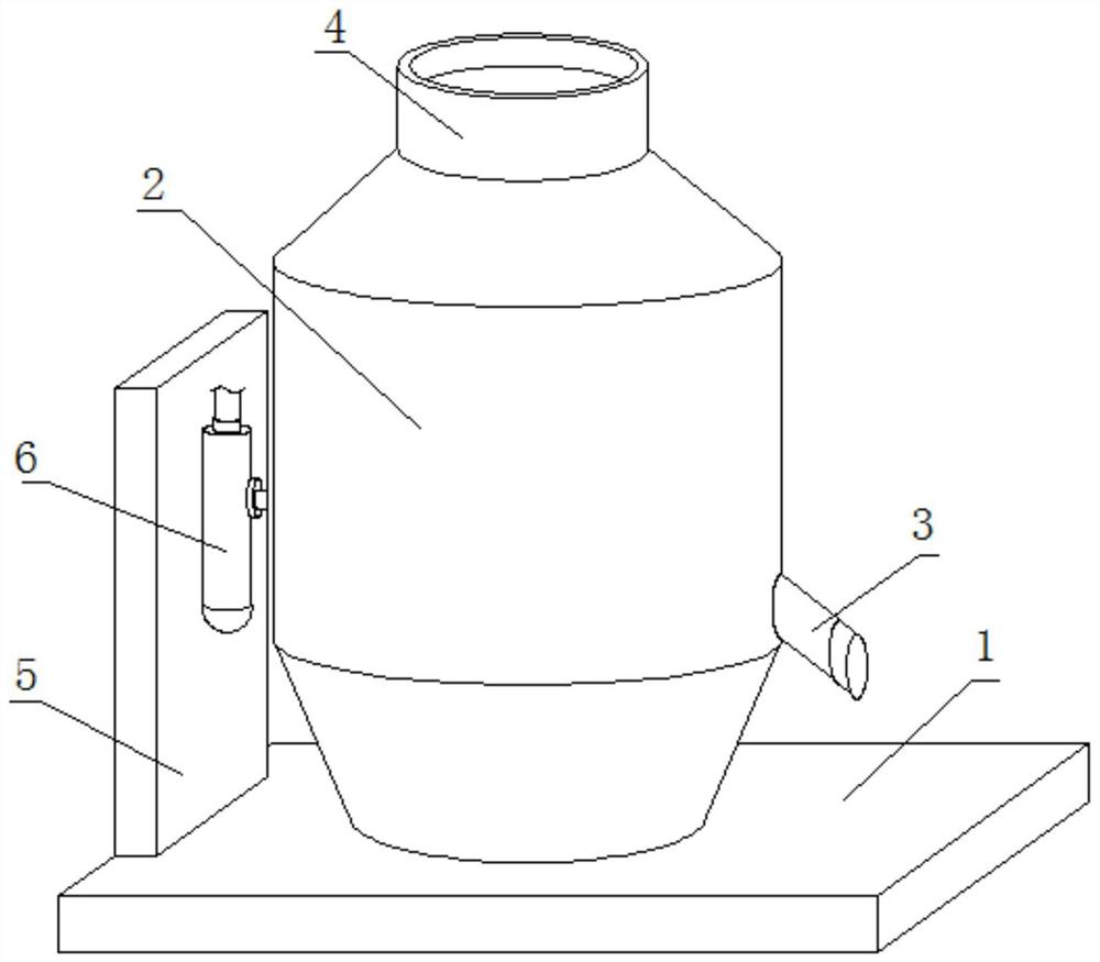
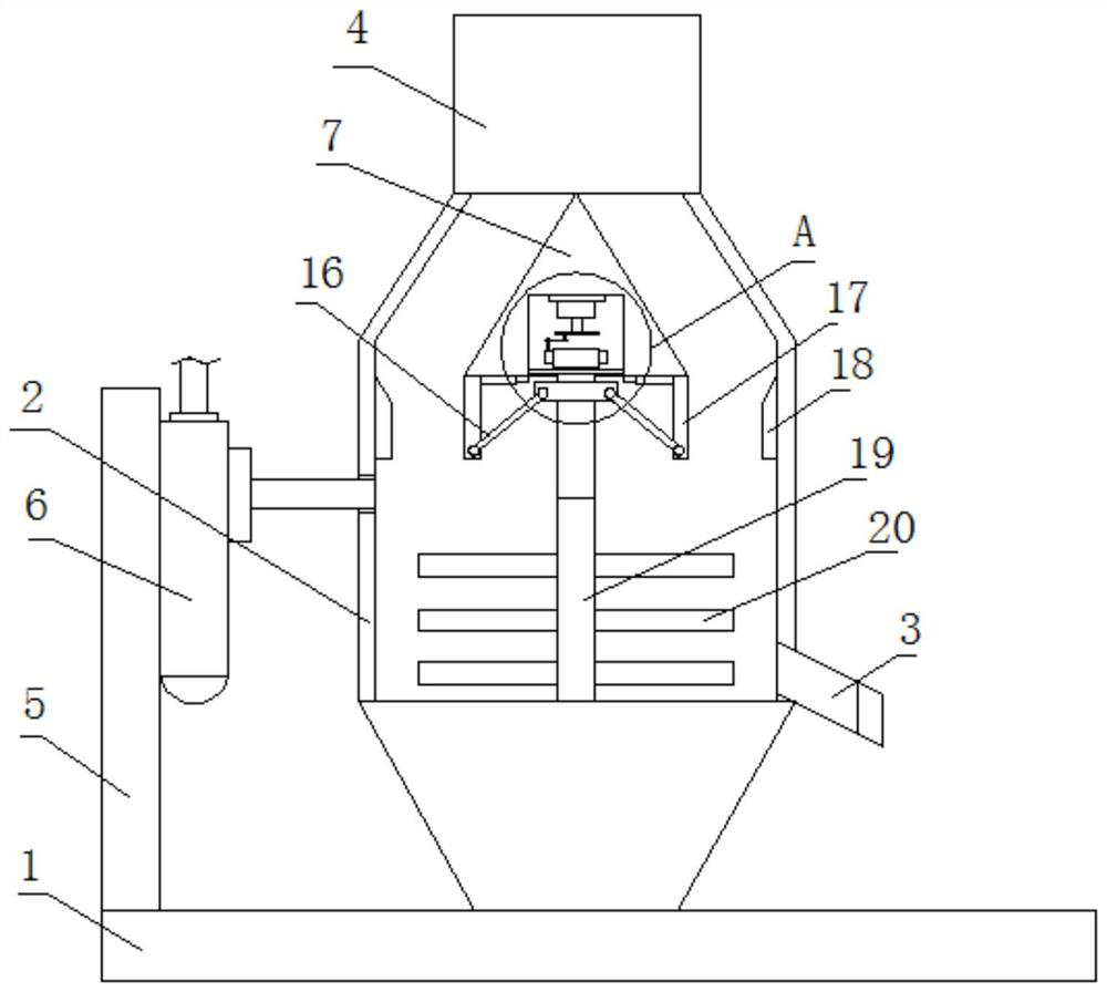
[0020]Refer toFigure 1-3, A latex paint mixing device, comprising a bottom plate 1, a mixing tank 2 is fixedly installed on the top of the bottom plate 1, a triangular plate 7 is fixedly installed on the inner wall of one side of the mixing tank 2, and a mounting groove 8 is opened at the bottom of the triangular plate 7. The groove 8 is provided with a driving mechanism. The driving mechanism is connected with a vertical shaft 13 for transmission, and the bottom of the vertical shaft 13 extends below the triangular plate 7. The vertical shaft 13 is threadedly connected with a threaded block 15 and one side of the threaded block 15 Two connecting rods 16 arranged symmetrically are rotatably installed. The bottoms of the two connecting rods 16 are both rotatably installed with pressure plates 17. The tops of the two pressure plates 17 are slidingly connected with the bottom of the triangular plate 7, and the inner walls of the mixing tank 2 are on both sides. A vertical plate 18 is f...

Embodiment 2

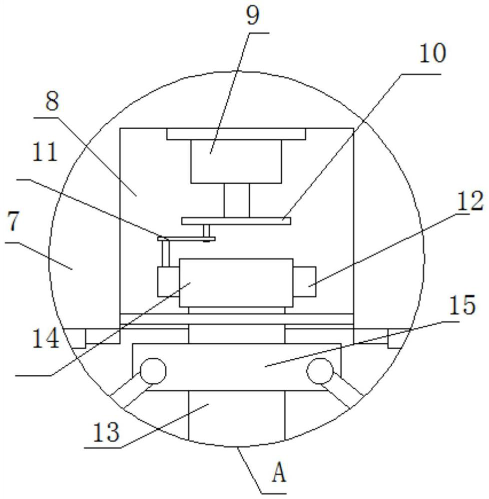
[0024]In the present invention, the drive mechanism includes a drive motor 9 fixedly mounted on the inner wall of the top of the mounting slot 8. The bottom of the output shaft of the drive motor 9 is fixedly mounted with a turntable 10, the bottom of the turntable 10 is rotatably mounted with an action rod 11, and the mounting slot 8 A rack 12 is slidably installed on the inner wall of one side. The top of the vertical shaft 13 extends to the inside of the mounting groove 8 and a gear 14 is fixedly sleeved. The gear 14 and the rack 12 mesh with each other, in order to realize the clockwise and the vertical shaft 13 Reciprocating counterclockwise rotation works.

[0025]In the present invention, the water inlet mechanism includes a mounting plate 5 fixedly mounted on the top of the bottom plate 1, a water inlet pump 6 is fixedly mounted on one side of the mounting plate 5, and the water outlet of the water inlet pump 6 is sealed and threaded with a water outlet pipe, a water outlet pip...


PUM


Abstract

The invention belongs to the field of blending equipment, particularly relates to a latex paint blending device, and aims at solving the problems that raw materials are directly added into a blendingtank in an existing emulsion paint blending process, the raw materials are not further crushed, raw material particles are large, and the blending quality and the blending efficiency of emulsion paintare influenced. A blending tank is fixedly mounted at the top of a bottom plate, a triangular plate is fixedly mounted on the inner wall of one side of the blending tank, a mounting groove is formedin the bottom of the triangular plate, a driving mechanism is arranged in the mounting groove, a vertical shaft is in transmission connection with the driving mechanism, and the bottom of the verticalshaft extends to a position below the triangular plate. A threaded block is in threaded connection with the vertical shaft, and two connecting rods are rotatably symmetrically installed on one side of the threaded rod. According to the latex paint blending device, the phenomenon that raw material particles are large is avoided, the latex paint mixing efficiency and quality are greatly improved, and blended latex paint conforms to the product standard.

Description

Technical field[0001]The invention relates to the technical field of blending equipment, in particular to a latex paint blending device.Background technique[0002]Latex paint is a common name for latex coatings. It was born in the middle and late 1970s. It is a large class of synthetic resin emulsion coatings represented by acrylic copolymer emulsions. Latex paint is a water-dispersible paint, which is made of synthetic resin emulsion as the base material, and the filler is ground and dispersed by adding various additives.[0003]The existing latex paint directly adds the raw materials to the mixing tank during the mixing process, without further crushing the raw materials, resulting in larger raw material particles, which affects the mixing quality and mixing efficiency of the latex paint, so we propose a latex paint The deployment device is used to solve the above-mentioned problems.Summary of the invention[0004]The purpose of the present invention is to solve the problem of latex pa...

Claims


Application Information

Patent Timeline
Patent Type & Authority Applications(China)
IPC IPC(8): B01F13/10B01F15/00
CPCB01F33/831B01F33/83612B01F35/00B01F35/321B01F2101/30
Inventor 钱国东
Owner WUXI LEHUA AUTOMATION TECH
Why Eureka
Try Eureka