A laser cleaning optical path

A laser cleaning and optical path technology, applied in the field of laser cleaning, can solve the problems of residual pollutants on the surface, affecting the cleaning effect, and large spacing, so as to avoid the residual pollutants, increase the coverage area, and improve the cleaning effect.

Active Publication Date: 2022-04-12
XIAMEN UNIV OF TECH
View PDF0 Cites 0 Cited by
  • Summary
  • Abstract
  • Description
  • Claims
  • Application Information

AI Technical Summary

Problems solved by technology

[0003] Existing laser cleaning usually uses a focused spot. After aligning the object to be cleaned with the linear spot, the two-dimensional plane cleaning of the object to be cleaned can be realized. If other areas of the plane need to be cleaned, the object to be cleaned needs to be moved Or linear spot, and the linear spot is usually presented in the form of a focal point, so that it moves in a "zigzag" shape during the scanning movement. Due to the influence of the spot or the moving speed of the object to be cleaned, the linear spot will The distance between switching is large, which leads to residual contamination on its surface and affects the cleaning effect

Method used


Image

  • A laser cleaning optical path
  • A laser cleaning optical path
  • A laser cleaning optical path

Examples


Embodiment Construction

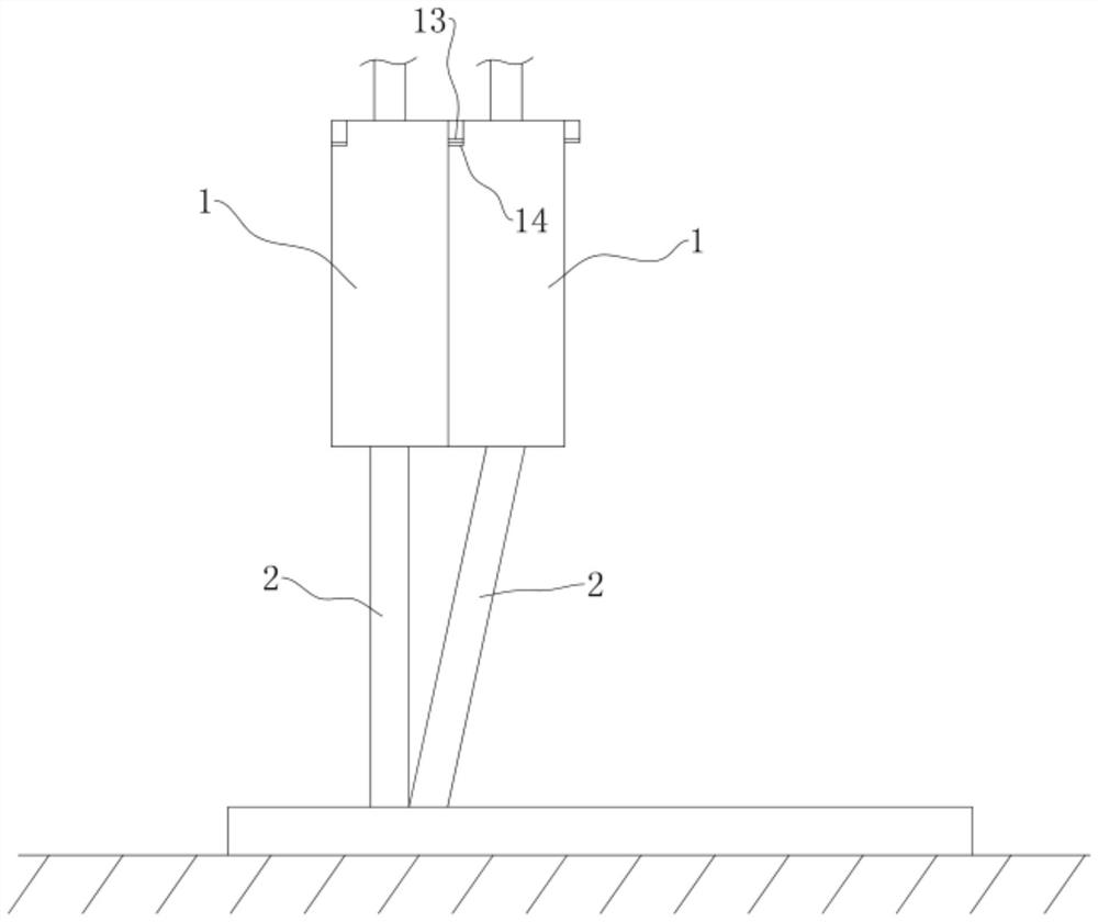
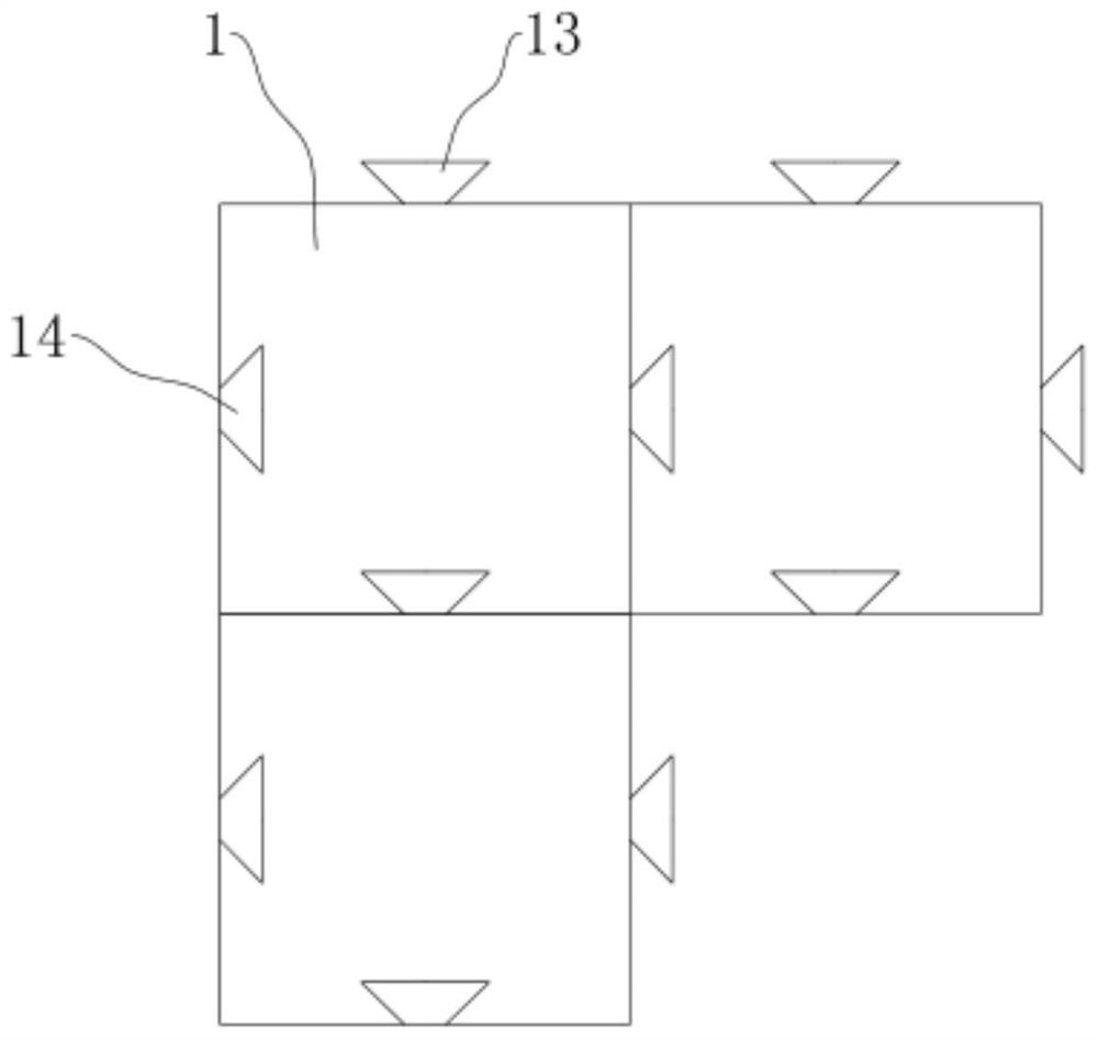
[0027] refer to Figure 1 to Figure 4 Further explain the optical path of laser cleaning.

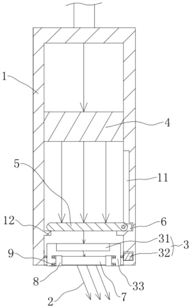
[0028] A laser cleaning optical path, such as figure 1 As shown, including the housing 1 that has just been spliced ​​together and the laser cleaning beam 2 disposed in the housing 1, the cross section of the housing 1 is set to a square shape, that is, it is formed into a square body, so that it can be spliced ​​along the front, rear, left, and right. Several shells 1 are sequentially spliced ​​in the X-axis or Y-axis direction, so that according to the cleaning surface requirements of the workpiece to be cleaned, they are sequentially spliced ​​to cover the width direction of the cleaning surface, and you can directly move multiple shells 1 along the length of the cleaning surface Direction movement does not need to form a "zigzag" movement, reducing the occurrence of spot switching, that is, no spacing error, avoiding residues of pollutants, and has the advantage of improving its la...


PUM


Abstract

The invention discloses a laser cleaning optical path, which relates to the technical field of laser cleaning. The main points of the technical solution are as follows: comprising a plurality of mutually spliced ​​shells and a laser cleaning beam arranged in the shell; For the adjusting member for adjusting the light-emitting angle of the laser cleaning beam, a plurality of the housings are sequentially spliced ​​in the X-axis or Y-axis direction, and after splicing, the laser cleaning beams converge on the same plane and are arranged next to each other. The invention can form a surface light spot and increase the laser coverage area after laser cleaning and focusing, thereby reducing the spacing error and avoiding the residue of pollutants in the process of switching regions, and has the advantage of improving the laser cleaning effect.

Description

technical field [0001] The invention relates to the technical field of laser cleaning, more specifically, it relates to a laser cleaning optical path. Background technique [0002] As an environmentally friendly, efficient, high-precision, and high-quality cleaning technology, laser cleaning can be used not only to clean organic pollutants, but also to clean inorganic substances, including metal rust, metal particles, dust, etc. An environmentally friendly way to clean. [0003] Existing laser cleaning usually uses a focused spot. After aligning the object to be cleaned with the linear spot, the two-dimensional plane cleaning of the object to be cleaned can be realized. If other areas of the plane need to be cleaned, the object to be cleaned needs to be moved Or linear spot, and the linear spot is usually presented in the form of a focal point, so that it moves in a "zigzag" shape during the scanning movement. Due to the influence of the spot or the moving speed of the obje...

Claims


Application Information

Patent Timeline
Patent Type & Authority Patents(China)
IPC IPC(8): B08B7/00G02B7/00G02B7/182
CPCB08B7/0042G02B7/00G02B7/1821
Inventor 袁和平陈水宣洪昭斌马林
Owner XIAMEN UNIV OF TECH
Why Eureka
Try Eureka