A cutting device for the production of a photoelectric optical fiber composite cable and a method of using the same

A cutting device and integrated cable technology, which is applied in metal processing and other directions, can solve the problems of uneven force on the cutting object, unusability, and uneven strength, and achieve the effect of improving the cutting effect, ensuring the cutting quality, and uniform force

Active Publication Date: 2022-03-15
深圳新海讯光电有限公司
View PDF8 Cites 0 Cited by
  • Summary
  • Abstract
  • Description
  • Claims
  • Application Information

AI Technical Summary

Problems solved by technology

[0004] The object of the present invention is to provide a cutting device for the production of photoelectric optical fiber composite cable, which solves the problem that the existing cutting device for the production of photoelectric optical fiber composite cable often uses a straight-up and straight-down cutting method, which not only has a general cutting effect, but also easily leads to cutting objects. The force is uneven, which leads to the extrusion of the cutting material and the reduction of the cutting quality; the existing cutting device for the production of optical fiber integrated cable is often simple in structure, and the cutting method of one-time force is used, resulting in uneven force during the cutting process, which is easy to damage the internal Therefore, the optical fiber cannot be used; the existing cutting device for the production of photoelectric optical fiber composite cable often lacks the problem of processing means for cutting waste

Method used


Image

  • A cutting device for the production of a photoelectric optical fiber composite cable and a method of using the same
  • A cutting device for the production of a photoelectric optical fiber composite cable and a method of using the same
  • A cutting device for the production of a photoelectric optical fiber composite cable and a method of using the same

Examples


Embodiment Construction

[0029] The technical solutions of the present invention will be clearly and completely described below in conjunction with the embodiments. Apparently, the described embodiments are only some of the embodiments of the present invention, not all of them. Based on the embodiments of the present invention, all other embodiments obtained by persons of ordinary skill in the art without creative efforts fall within the protection scope of the present invention.

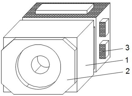
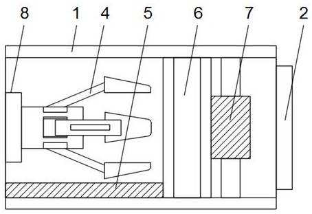
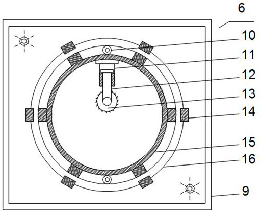
[0030] see Figure 1-5 As shown, a cutting device for the production of photoelectric optical fiber composite cable comprises a cutting box 1, a feed tray 2 is installed on the front end of the cutting box 1, two groups of motors-3 are installed on one side of the cutting box 1, and the inner side of the cutting box 1 Transport ring 7 is installed, and the inboard of cutting box 1 is equipped with cutting assembly 6 and separation assembly 4, and cutting assembly 6 is positioned at the side of separation assembly 4, and the...


PUM


Abstract

The invention discloses a cutting device for the production of photoelectric optical fiber composite cable, which comprises a cutting box, a feeding tray is installed on the front end of the cutting box, two sets of motors are installed on one side of the cutting box, and two sets of motors are installed on the inside of the cutting box. A transport ring is installed, and a cutting assembly and a separation assembly are installed on the inside of the cutting box. The cutting assembly is located on one side of the separation assembly. disk, the middle part of the shock-absorbing and stable disk is equipped with a fixed ring and a movable ring, the movable ring is located inside the fixed ring, and several groups of clamping arms are installed between the movable ring and the fixed ring, and the outer side of the movable ring Two sets of friction runners are installed. The invention cooperates with the high-speed rotation to improve the cutting effect, and can make the cutting object bear uniform force, ensure the cutting quality, and ensure the reusability of various materials in the optical fiber composite cable.

Description

technical field [0001] The invention belongs to the field of photoelectric optical fiber integrated cable processing, and in particular relates to a cutting device for producing a photoelectric optical fiber integrated cable and a use method thereof. Background technique [0002] Photoelectric optical fiber integrated cable is suitable for broadband access network system as a transmission line. It is a new type of access method. It integrates optical fiber and power transmission copper wire, and can solve the problems of broadband access, equipment power consumption, and signal transmission. The processing of photoelectric optical fiber composite cable needs to use professional cutting device for cutting work. [0003] The existing cutting devices for the production of photoelectric optical fiber composite cables have certain disadvantages. The existing cutting devices for the production of photoelectric optical fiber composite cables often use a straight-up and straight-dow...

Claims


Application Information

Patent Timeline
Patent Type & Authority Patents(China)
IPC IPC(8): B21F11/00B26D1/147B26D7/18
CPCB21F11/00B26D1/147B26D7/18
Inventor 吴海平肖庆强
Owner 深圳新海讯光电有限公司
Why Eureka
Try Eureka