

Portable woodworking edge bonding machine
An edge banding machine, portable technology, applied in wood processing appliances, household components, etc., can solve problems such as difficult operation, increased cost, and increased operation complexity
- Summary
- Abstract
- Description
- Claims
- Application Information
AI Technical Summary
Problems solved by technology
Method used
Image

Examples
Embodiment 1
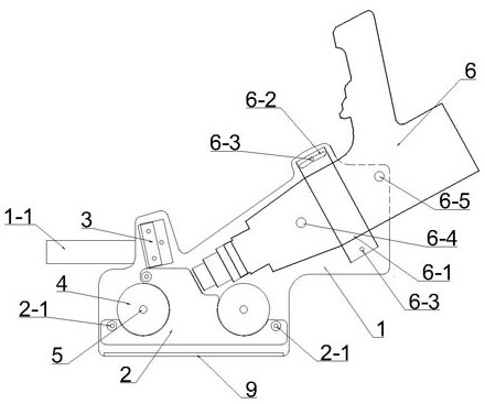
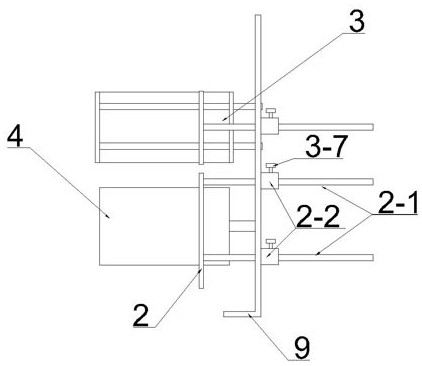
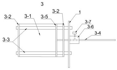
[0065] Such as figure 1 , figure 2 , image 3 , Figure 4 , Figure 5 , Figure 6 , Figure 7 , Figure 8 , Figure 9 , Figure 10 , Figure 11 A portable woodworking edge banding machine is shown, including: base plate 1, handle 1-1, baffle plate 2, connecting rod 2-1, connecting rod positioner 2-2, concave groove 3, concave groove bottom plane 3 -1, concave groove side elevation 3-2, fixed rod 3-3, adjusting rod 3-4, guide groove adjusting plate 3-5, adjusting locator 3-6, positioning screw 3-7, pressure wheel 4, Pressing roller shaft 5, hot air generating device 6, positioning hoop 6-1, arc strip hole 6-2, adjusting screw 6-3, front adjusting screw 6-4, rear adjusting screw 6-5, edge banding strip 7, door frame Outer L-shaped facade 8, L-shaped wide facade 8-1, L-shaped narrow facade 8-2, L-shaped top facade 8-3, backing 9, paint-free wood board 10.
[0066] See figure 1 , the substrate 1 described in the present embodiment is a thin steel plate with a thicknes...
Embodiment 2
[0092] See Figure 11 Carry out edge sealing to the paint-free woodworking board 10.
[0093] Lay the paint-free woodworking board 10 flat with the edge to be sealed facing up. Choose the edge banding strip 7 that is slightly wider than the edge to be sealed of the paint-free woodworking board 10, cut a section of the edge banding strip 7 that is slightly longer than the waiting edge of the paint-free woodworking board 10 and be coated with hot melt adhesive, and connect its end The hot-melt adhesive surface faces the heat gun 6, and passes through the adjustable guide groove to the bottom of the pressure roller 4.
[0094] Pull the adjustment rod 3-4, the guide groove adjustment plate 3-5 slides in the concave groove 3, thereby increasing or reducing the width of the concave groove 3, making the width of the concave groove 3 It cooperates with the edge strip 7 in a gap, and positions the edge strip 7 on the side of the adjustable guide groove 3 close to the base plate 1, an...
PUM
 Abstract
Description
Claims
Application Information