
Substrate glass cutting and grinding device

A glass cutting and grinding device technology, applied in grinding devices, grinding machine tools, glass production, etc., can solve the problems of chipping, chipping, chipping, hard damage, different cutting depths, etc., and achieve the effect of improving stability

Active Publication Date: 2021-03-02
彩虹(合肥)液晶玻璃有限公司
View PDF15 Cites 7 Cited by
  • Summary
  • Abstract
  • Description
  • Claims
  • Application Information

AI Technical Summary

Problems solved by technology

[0003] The existing technology has the following problems: during the cutting and grinding process of substrate glass, the cutting ability of the cutting wheel decreases after a period of use, and discontinuous deep scribing occurs when breaking, chipping, and fragmentation occur; in addition For different thicknesses, the cutting pressure changes, resulting in different cutting depths. Usually, it is necessary to replace the cutting wheel to eliminate it. The higher the cutting quality requirements, the replacement frequency is about obvious. Usually, the length of the replacement cutting glass is between 2500m and 3000m. During the cutting process, there will be relatively serious deterioration. At the same time, during the cutting process, the cutting and grinding wheel is in direct contact with the substrate glass, which is likely to cause hard damage during direct contact.

Method used


Image

  • Substrate glass cutting and grinding device
  • Substrate glass cutting and grinding device
  • Substrate glass cutting and grinding device

Examples


Embodiment Construction

[0024] The following will clearly and completely describe the technical solutions in the embodiments of the present invention with reference to the accompanying drawings in the embodiments of the present invention. Obviously, the described embodiments are only some, not all, embodiments of the present invention. Based on the embodiments of the present invention, all other embodiments obtained by persons of ordinary skill in the art without making creative efforts belong to the protection scope of the present invention.

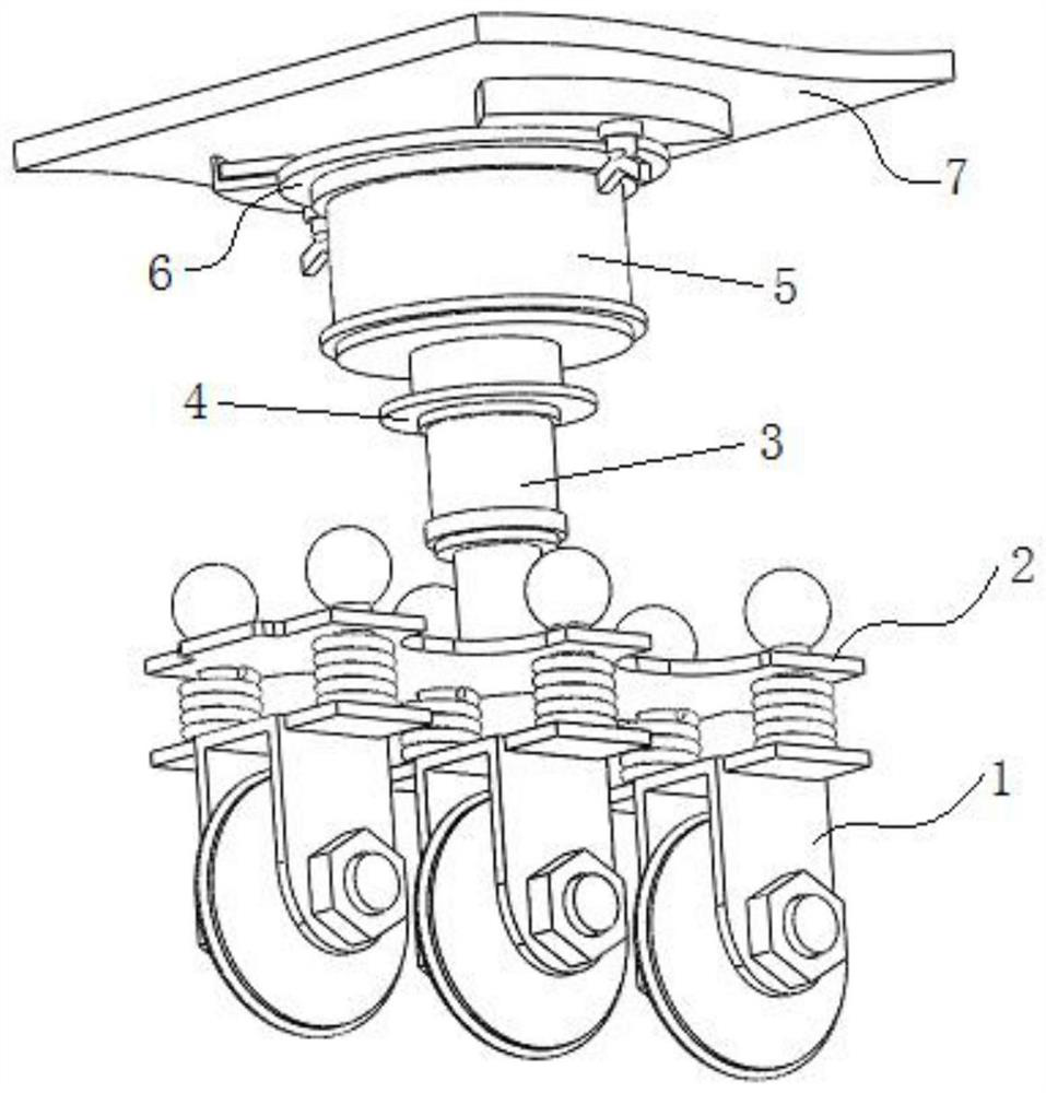
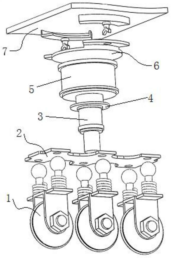
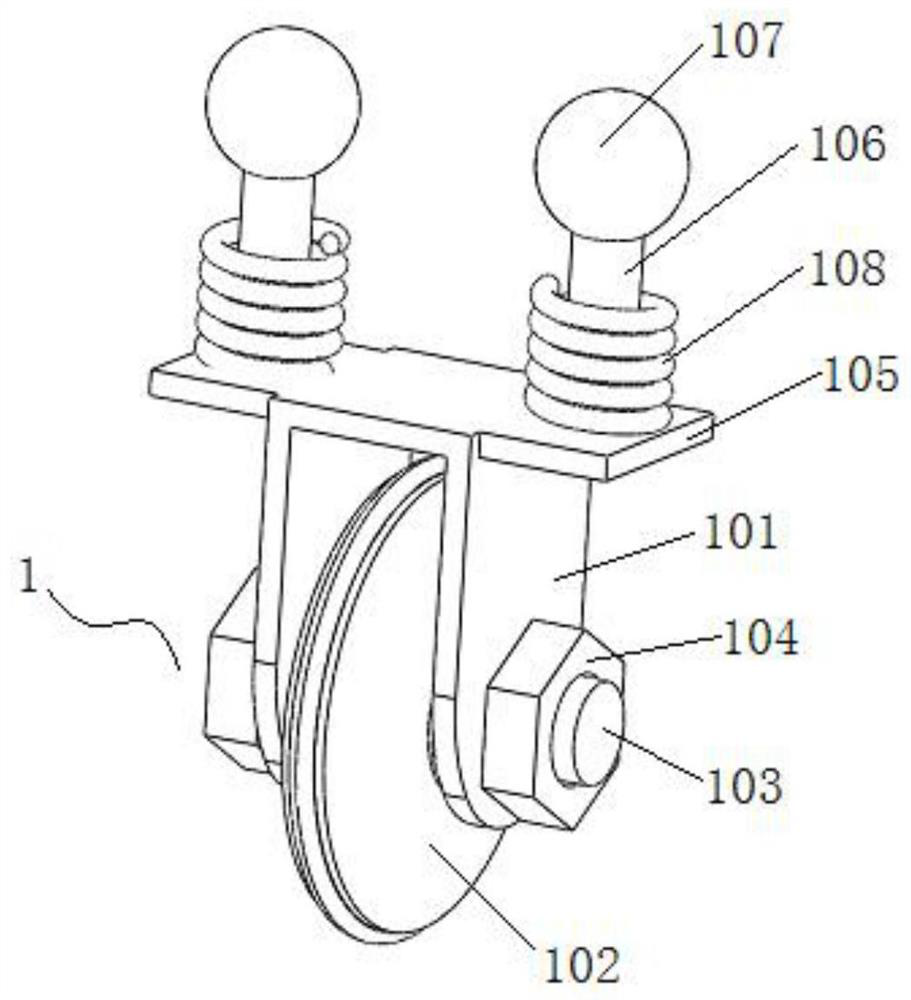
[0025] see Figure 1-6 , the present invention provides the following technical solutions: a substrate glass cutting and grinding device, including multiple sets of substrate cutting knife assemblies 1, multiple sets of substrate cutting knife assemblies 1 are elastically pressed and slidably installed on the pressure limiting plate assembly 2, and the pressure limiting plate assembly 2 The bit plate assembly 2 is fixed on the bottom cylinder body of the autom...


PUM


Abstract

The invention discloses a substrate glass cutting and grinding device. The device comprises a plurality of substrate cutting knife assemblies, and the plurality of substrate cutting knife assemblies are installed on pressurizing limiting plate assemblies in an elastic abutting sliding mode. The device has the beneficial effects that a top cutting air cylinder drives the substrate cutting knife assemblies to move downwards in the cutting process, at the moment, cutting knife discs on the substrate cutting knife assemblies make contact with the surface of the substrate glass, the cutting pressurizing force applied to the substrate glass during cutting of the substrate cutting knife assemblies is changed through fine adjustment of an automatic pressurizing air cylinder, and through elastic abutting of an ejecting guide sliding rod and an ejecting pressurizing spring, the knife bodies of the cutting knife discs elastically jack and move relative to plate bodies of the pressurizing limitingplate assemblies; and the knife bodies of the cutting knife discs on the multiple substrate cutting knife assemblies elastically jack and move relative to the plate bodies of the pressurizing limiting plate assemblies, during cutting, the knife bodies of the cutting knife discs on the multiple substrate cutting knife assemblies are in elastic jacking and pressing contact with a substrate glass plate, and in this way, flexible contact is achieved when the multiple substrate cutting knife assemblies make contact with the substrate glass plate.

Description

technical field [0001] The invention belongs to the technical field of substrate glass manufacturing equipment, and in particular relates to a substrate glass cutting and grinding device. Background technique [0002] Substrate is the abbreviation of thin film transistor. Substrate display is the mainstream display device on various notebook computers and desktop computers. Each liquid crystal pixel on this type of display is driven by a thin film transistor integrated behind the pixel. Therefore Substrate display is also a kind of active matrix liquid crystal display device, and it is one of the best LCD color displays. Substrate display has the advantages of high responsiveness, high brightness, high contrast, etc., and its display effect is close to that of CRT display. [0003] The existing technology has the following problems: during the cutting and grinding process of substrate glass, the cutting ability of the cutting wheel decreases after a period of use, and discon...

Claims


Application Information

Patent Timeline
IPC IPC(8): B28D1/24B28D7/00B24B37/00B24B37/34
CPCB28D1/24B28D7/00B24B37/00B24B37/34Y02P40/57
Inventor 付丽丽
Owner 彩虹(合肥)液晶玻璃有限公司
Learn More