Intelligent liftable new energy vehicle charging pile

A technology of new energy vehicles and charging piles, which is applied in the direction of electric vehicle charging technology, charging stations, electric vehicles, etc., can solve the problems of unresolved separation of charging piles, weakening user experience, etc., to ensure display effect, ensure normal use, Optimize the effect of the process of use

Inactive Publication Date: 2021-03-02
阜阳扬宇充电设备有限公司
View PDF0 Cites 0 Cited by
  • Summary
  • Abstract
  • Description
  • Claims
  • Application Information

AI Technical Summary

Problems solved by technology

It includes a guide rail and a charging device that can move along the guide rail. The charging device includes a pile body. The bottom of the pile body is provided with a lateral movement mechanism that can move along the guide rail. There is a charging arm, and the pile body is provided with a lifting mechanism that can drive the charging arm up and down and a rotating mechanism that can drive the charging arm to rotate vertically. The charging arm includes a controller, a charging head, and a first driving mechanism that can drive the charging head to move forward and backward. The second driving mechanism that can drive the charging head to rotate horizontally, the charging head is equipped with a camera, and the controller is electrically connected to the lateral moving mechanism, the lifting mechanism, the rotating mechanism, the first driving mechanism, the second driving mechanism, and the camera; the technical solution It can locate the charging socket of the electric vehicle by itself, and automatically insert the charging head into the charging socket of the electric vehicle to realize automatic charging without manual operation, which brings great convenience to the user; The area is separated, and the damaged charging pile is difficult to be directly found by the users driving and charging, which weakens their use experience

Method used


Image

  • Intelligent liftable new energy vehicle charging pile
  • Intelligent liftable new energy vehicle charging pile
  • Intelligent liftable new energy vehicle charging pile

Examples


Embodiment approach

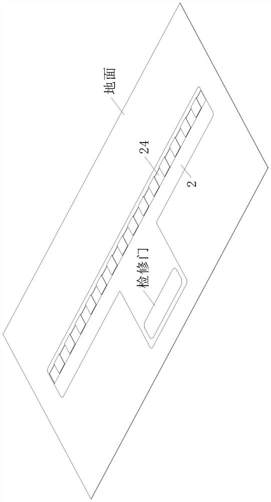
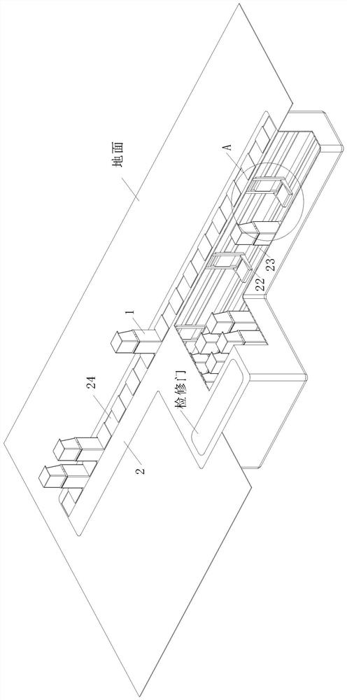
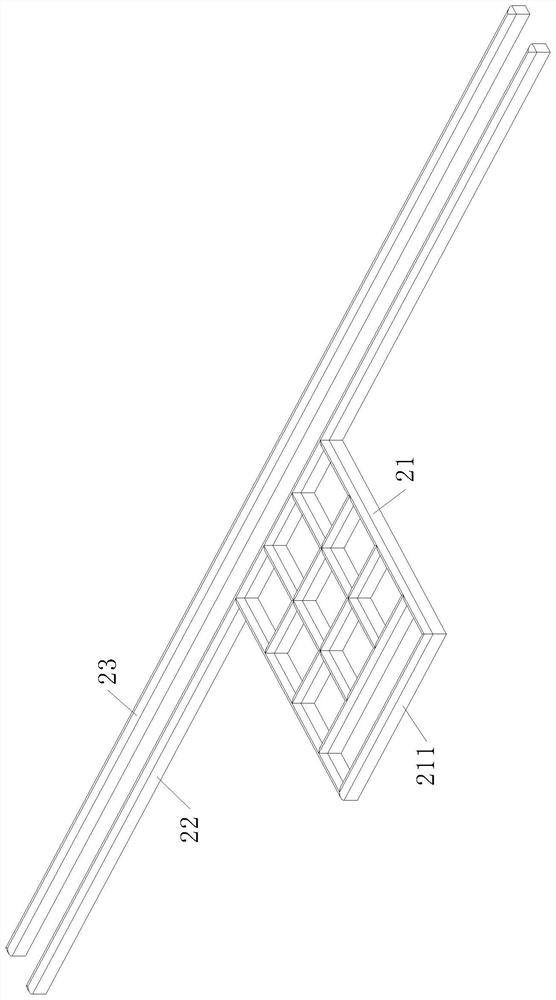
[0026] As an embodiment of the present invention, an inspection frame 211 connected to the outside of the mobile network frame 21 is also provided, and an inspection door is installed on the top of the charging pile warehouse 2 where the inspection frame 211 is located; the charging pile body 1 is moving The number on the grid frame 21 is greater than the number of charging positions on the charging rail 23. When the charging pile body 1 fails and is damaged during use; the controller of the charging pile library 2 will drive and damage the charging pile body 1. 3. Transfer it to the maintenance rack 211; the charging pile will break down during use and lose the charging function of its parking space, and it is difficult to directly find the faulty charging pile in an unrepaired state, and it will park the new energy vehicle at the charging position The process causes waste and affects the user experience; by setting multiple charging piles 1 in the mobile grid 21, when a fault...


PUM


Abstract

The invention relates to the technical field of charging piles, in particular to an intelligent liftable new energy vehicle charging pile which comprises a charging pile body, a charging pile libraryand a controller. When the lifting type charging pile is not used, the lifting type charging pile needs to be lowered to a charging pile library preset underground, and the fixed position of the lifting type charging pile needs to control the posture of a vehicle during parking, so that wire connection of the charging pile is facilitated, the experience of a charging user is reduced, and the actual use effect of the charging pile is further affected; therefore, the multiple charging pile bodies arranged in the charging pile library are matched with the movable rail and the brackets mounted onthe charging rail, and the ascending positions of the charging pile bodies on the charging rail are controlled to be aligned to the parking posture of the to-be-charged automobile according to the parking state of the automobile in the parking lot; therefore, the interference to the area of the parking lot is reduced, the charging operation time is saved, and the use effect of the intelligent liftable new energy automobile charging pile is improved.

Description

technical field [0001] The invention relates to the technical field of charging piles, in particular to an intelligent and liftable charging pile for new energy vehicles. Background technique [0002] Under the pressure of energy and environmental protection, new energy vehicles will undoubtedly become the development direction of future vehicles. Compared with gas stations for ordinary fuel vehicles, the popularity of charging piles also affects the charging of new energy vehicles. The functions of charging piles are similar The fuel dispenser in the gas station can be fixed on the ground or wall, installed in the parking lot or charging station of public buildings and residential areas, and can charge various types of electric vehicles according to different voltage levels. [0003] The charging pile protrudes from the ground of the parking lot, which divides the open parking lot and weakens the efficiency of vehicle movement in the parking lot. space, but its fixed base ...

Claims


Application Information

Patent Timeline
Patent Type & Authority Applications(China)
IPC IPC(8): B60L53/31
CPCB60L53/31Y02T10/70Y02T10/7072Y02T90/12
Inventor 张大朋麻大伟鹿冬冬
Owner 阜阳扬宇充电设备有限公司
Why Eureka
Try Eureka