Rotor wing brake control device with locking mechanism and method

A control device and rotor technology, which is applied in the field of rotor brake control devices, can solve the problems of difficult detection of hydraulic component failures, heavy weight of the hydraulic brake system, and large structural space occupied, and achieve convenient and efficient braking and brake release actions and accurate control , the effect of taking up little space

Pending Publication Date: 2021-03-02
ZHONGHANG ELECTRONICS MEASURING INSTR
View PDF7 Cites 0 Cited by
  • Summary
  • Abstract
  • Description
  • Claims
  • Application Information

AI Technical Summary

Problems solved by technology

[0003] At present, the helicopter rotor brake device adopts hydraulic brake system or gear transmission brake device. The hydraulic brake system has the disadvantages of heavy weight, slow response and difficult maintenance, and the failure of hydraulic components is not easy to detect, and there are disadvantages such as hydraulic oil leakage and combustion.
The gear transmission brake device has the disadvantages of occupying a large structural space, small braking torque feedback, low braking efficiency, and cumbersome operation.

Method used


Image

  • Rotor wing brake control device with locking mechanism and method
  • Rotor wing brake control device with locking mechanism and method
  • Rotor wing brake control device with locking mechanism and method

Examples


Embodiment Construction

[0031] The present invention is described in further detail below in conjunction with accompanying drawing:

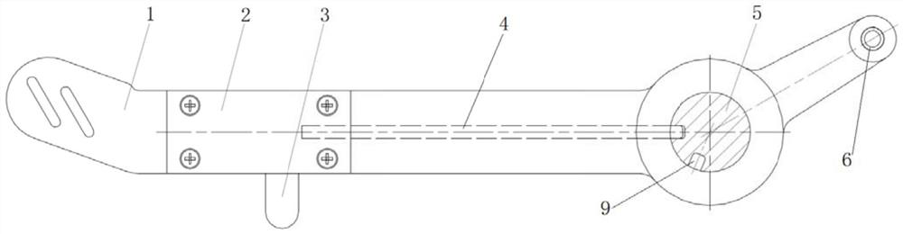
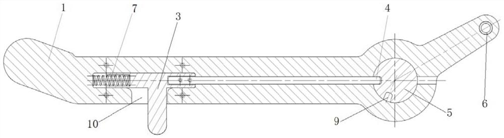
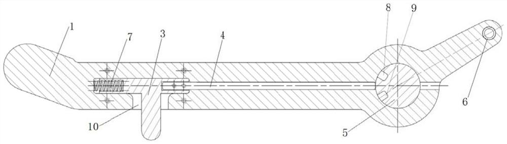
[0032] Such as figure 1 Shown is the rotor brake control device with a locking mechanism according to the present invention, which includes a brake handle 1 , a rotating shaft 5 and a slider 3 .

[0033] The front end of the brake handle 1 is a gripping end, which is used for the operator to hold and operate. The braking torque is directly transmitted to the operator by the brake handle 1, and the feedback is direct. A radial bushing 6 is arranged at the end of the brake handle 1 , and the transmission wire harness is arranged in the bushing 6 . The brake handle 1 is provided with a radial through hole, and the through hole is located near the end of the brake handle 1 . The rotating shaft 5 is arranged in the through hole and is rotationally connected with the brake handle 1 . The stroke of the transmission wire harness can be controlled by adjusting the distance b...


PUM


Abstract

The invention discloses a rotor wing brake control device with a locking mechanism and a method. The rotor wing brake control device comprises a brake handle, a rotating shaft and a sliding block. A transmission wire harness is arranged at the tail end of the brake handle; a radial through hole is formed in the brake handle; the rotating shaft is arranged in the through hole and is rotationally connected with the brake handle; a radial brake releasing groove and a radial brake groove are formed in the circumferential surface of the rotating shaft, and the direction, relative to the brake releasing groove, of the brake groove is consistent with the rotating direction of the brake handle during braking; an inner cavity is formed in the brake handle, and the tail end of the inner cavity communicates with the through hole; a radial sliding groove is formed in the brake handle and is communicated with the inner cavity; the sliding block comprises a horizontal section and a vertical sectionwhich are perpendicular to each other, the horizontal section is slidably connected into the inner cavity, and the tail end of the horizontal section is embedded into the brake releasing groove or thebrake groove; and the vertical section extends out of the brake handle from the sliding groove. Pure mechanical parts are adopted, occupied space is small, weight is light, operation is easy, feedback is direct, and man-machine work efficiency is good.

Description

technical field [0001] The invention belongs to the field of helicopter transmission, and relates to a rotor brake control device and method with a locking mechanism. Background technique [0002] Helicopters use rotors to provide helical lift as a power source. To stop the rotors from rotating quickly after parking, the rotors need to be braked. The rotor brake control device controls the brake mechanism through the transmission line, performs braking and brake release actions, and controls the brake position and brake release position. [0003] At present, the helicopter rotor brake device adopts hydraulic brake system or gear transmission brake device. The hydraulic brake system has the disadvantages of heavy weight, slow response and difficult maintenance, and the failure of hydraulic components is not easy to detect, and there are disadvantages such as hydraulic oil leakage and combustion. The gear transmission braking device has the disadvantages of occupying a large ...

Claims


Application Information

Patent Timeline
Patent Type & Authority Applications(China)
IPC IPC(8): B64C27/32B64C27/54B64C27/59
CPCB64C27/32B64C27/54B64C27/59
Inventor 常飞白新玉孙敬先薛振华黄义敏
Owner ZHONGHANG ELECTRONICS MEASURING INSTR
Why Eureka
Try Eureka