A radial double-winding switched reluctance motor for electric vehicles and its power converter

A switched reluctance motor and power converter technology, applied in electric vehicles, electric components, AC motor control, etc., can solve the problem of not improving the power density and efficiency of the motor, increasing the torque and speed regulation range, increasing the structure or winding complexity In order to improve the motor efficiency, shorten the excitation circuit, reduce the supersaturation of the flux linkage and mutual interference

Active Publication Date: 2021-11-23
JIANGSU UNIV
View PDF16 Cites 0 Cited by
  • Summary
  • Abstract
  • Description
  • Claims
  • Application Information

AI Technical Summary

Problems solved by technology

But in fact, the above-mentioned two published patent technologies only increase the complexity of the structure or winding to increase the torque and speed regulation range. In essence, they can be regarded as two motors, which can move independently or in parallel, so Both do not improve the power density and efficiency of the motor

Method used


Image

  • A radial double-winding switched reluctance motor for electric vehicles and its power converter
  • A radial double-winding switched reluctance motor for electric vehicles and its power converter
  • A radial double-winding switched reluctance motor for electric vehicles and its power converter

Examples


Embodiment Construction

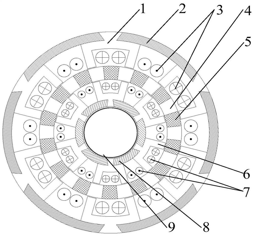
[0026] see figure 1 , a radial double-winding switched reluctance motor for an electric vehicle according to the present invention, comprising an outer segmented stator 1, a non-magnetically conductive outer shell 2, an outer winding 3, a trapezoidal segmented rotor 4, a non-magnetically conductive trapezoidal block 5, Inner block stator 6 , inner winding 7 , non-magnetic inner shell 8 and rotating shaft 9 . The outermost part is the outer block stator 1 and a non-magnetic outer casing 2, the non-magnetic outer casing 2 is cylindrical, and the side wall of the non-magnetic outer casing 2 is evenly embedded in the circumferential direction s Outer block stator 1, N s The structures of the two outer segmented stators 1 are exactly the same, the outer diameter of the outer segmented stator 1 is equal to the outer diameter of the non-magnetic conduction outer shell 2, but the inner diameter is smaller than the inner diameter of the non-magnetic conduction outer shell 2. Such as ...


PUM


Abstract

The invention discloses a radial double-winding switched reluctance motor for an electric vehicle and a power converter thereof. Each outer block stator consists of an outer stator trapezoidal inlay area, an outer stator yoke and an outer Composed of excitation teeth, each outer excitation tooth is wound with an outer winding, and the rotor ring is composed of N r A trapezoidal segmented rotor and non-magnetically conductive trapezoidal blocks are alternately distributed along the circumferential direction, and each inner segmented stator is composed of an inner stator trapezoidal inlay area, an inner stator yoke and an inner excitation tooth that are sequentially connected from the inside to the outside; Taking phase A as an example, the negative terminal of the phase winding A1 in the inner winding is connected to the positive terminal of the phase winding A2 in the outer winding and the positive pole of the diode D1 at the same time, and the negative terminal of the phase winding A2 is connected to the source of the power switch tube V2 , the phase windings A2, B2, and C2 in the outer winding are connected in parallel with an added power switch tube, which can realize fast demagnetization, improve output torque, power density and efficiency, and broaden the driving mode and speed regulation range of the motor.

Description

technical field [0001] The invention relates to the technical field of motor manufacturing and application, in particular to a switched reluctance motor structure and a matching power converter capable of improving its power density and efficiency. Background technique [0002] The switched reluctance motor is a DC motor that realizes the rotation of the motor by switching the on-phase in turn. Because of its simple structure, it does not require permanent magnets containing rare earth materials, and has good robustness, large starting torque, small starting current and high efficiency. , good speed regulation performance, suitable for frequent start and stop occasions and many other advantages, it has been widely concerned in electric vehicles. However, traditional switched reluctance motors have lower power density and efficiency compared with permanent magnet motors because they have no permanent magnets and produce negative torque during demagnetization. These shortcomin...

Claims


Application Information

Patent Timeline
Patent Type & Authority Patents(China)
IPC IPC(8): H02K16/04H02P25/18H02K11/33H02K3/52H02K1/14
CPCH02K1/146H02K3/522H02K16/04H02P25/18H02K11/33Y02T10/64
Inventor 孙晓东陈宗哲邬江陵陈龙田翔
Owner JIANGSU UNIV
Why Eureka
Try Eureka