
Screw and rubber cap assembling device and method

A technology for assembling devices and rubber caps, applied in metal processing, metal processing equipment, manufacturing tools, etc., can solve the problems of difficult clamping and assembly, soft rubber caps, etc., and achieve the effects of improving efficiency, facilitating processing, and preventing falling

Inactive Publication Date: 2021-03-05
温州锐翔装饰工程有限公司
View PDF1 Cites 0 Cited by
  • Summary
  • Abstract
  • Description
  • Claims
  • Application Information

AI Technical Summary

Problems solved by technology

[0005] The purpose of the present invention is to solve the problem that the texture of the rubber cap is soft and difficult to clamp and assemble in the prior art, and propose a screw rubber cap assembly device that is reliable in removing the rubber cap and can be assembled accurately

Method used


Image

  • Screw and rubber cap assembling device and method
  • Screw and rubber cap assembling device and method
  • Screw and rubber cap assembling device and method

Examples


Embodiment Construction

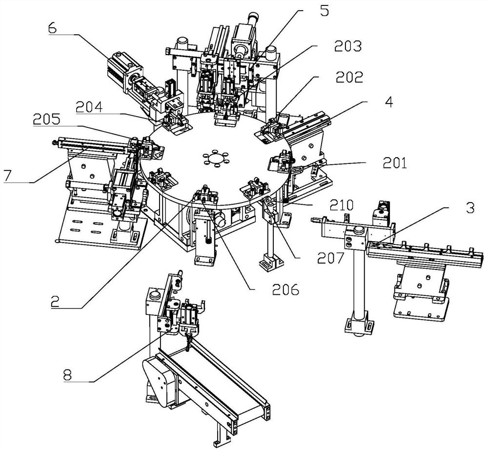
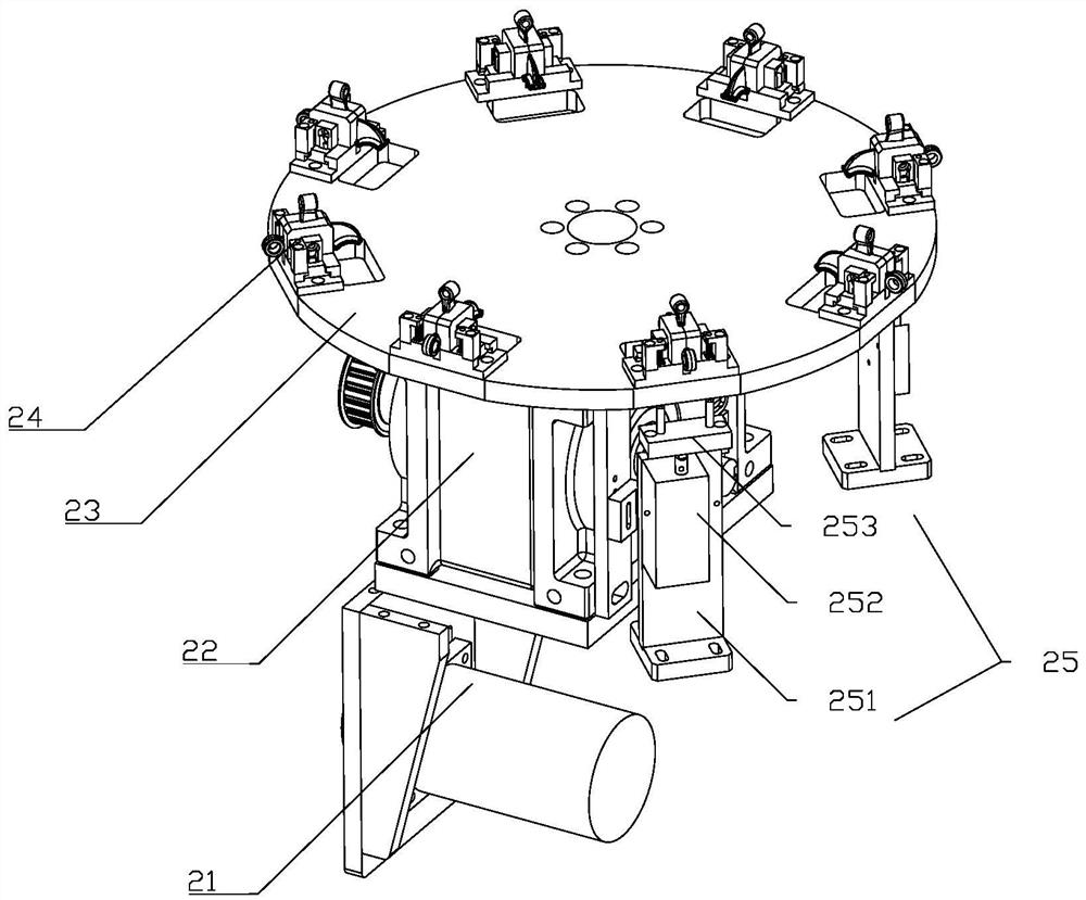
[0026] Such as figure 1 As shown, a doorstop assembly machine includes a frame and a fixture rotating device 2 installed on the frame, a substrate feeding device 3, a foot assembly device 4, a screw assembly device 5, a rubber cap assembly device 6, a rotating sleeve Device assembly 7 and finished product unloading device 8; The described jig rotating device 2 is positioned at the center of the frame, and the jig rotating device 2 is in the shape of a circle, and a week of the jig rotating device 2 is provided with a plurality of stations, respectively for the upper The material station 201 is the first assembly station 202, the second assembly station 203, the third assembly station 204, the fourth assembly station 205, the blanking station 206 and the detection station 207; the substrate feeding device 3 corresponds to the upper The material station 201, the foot assembly device 4 corresponds to the first assembly station 202, the screw assembly device 5 corresponds to the ...


PUM


Abstract

The invention discloses a screw and rubber cap assembling device. The screw and rubber cap assembling device comprises a support, a jacking-in air cylinder, a jacking column, a material receiving base, a material stopping block, a limiting fork and a vertical air cylinder, wherein the jacking-in air cylinder is fixed to the side of the upper end of the support, the jacking column is connected to asliding block, the sliding block is movably connected to the support, and the sliding block is connected with the telescopic end of the jacking-in air cylinder; a thin shaft is arranged at the end part of the jacking column; the material receiving seat is fixed on the support; and a connecting base is arranged at the upper end of the material receiving base, the vertical air cylinder is fixed tothe connecting base, a connecting plate is arranged at the telescopic end of the vertical air cylinder, and a material stopping block and a limiting fork are both arranged at the lower end of the connecting plate. The screw and rubber cap assembling device has the advantages of being reliable in rubber cap moving and taking and accurate in assembling.

Description

technical field [0001] The invention relates to the technical field of doorstop assembly, in particular to a screw cap assembly device and a doorstop assembly machine. Background technique [0002] A door stop is a barrier used to block a door to keep it open or closed. Such as Figure 8 The door stop shown is composed of a base body 100, a foot 200, a screw 300, a rubber cap 400 and a rotating sleeve 500. The base body 100 is provided with a hinge hole 101, and the rotation sleeve 500 is interference fit in the hinge hole 101; the base body 100 There is a threaded hole 102 on the top, and the screw 300 is screwed into the threaded hole 102. The rubber cap 400 is set on the end of the screw 300, and the screw 300 is used as the power input part; The connection part 103 of the base body 100 . When this doorstop is in use, the rotating sleeve 500 is hinged on the ground, the rubber cap 400 corresponds to the side of the door, and the foot 200 corresponds to the ground. impa...

Claims


Application Information

Patent Timeline
Patent Type & Authority Applications(China)
IPC IPC(8): B23P19/06B23P19/00B23P19/027
CPCB23P19/00B23P19/001B23P19/027B23P19/06
Inventor 王从相许麦云许梅菊
Owner 温州锐翔装饰工程有限公司
Learn More