Supercharge Your Innovation With Domain-Expert AI Agents!

Metal foil laminated board, printed circuit board and manufacturing method of metal foil laminated board

A metal foil, laminated board technology, applied in printed circuits, printed circuits, printed circuit components, etc., can solve problems such as easy deformation

Active Publication Date: 2021-03-05
TAIWAN POWDER TECH CO LTD
View PDF10 Cites 0 Cited by
  • Summary
  • Abstract
  • Description
  • Claims
  • Application Information

AI Technical Summary

Problems solved by technology

[0005] In view of the above technical problems, the present invention provides a metal foil laminate, which is obtained by combining the fluoropolymer laminate without reinforcing cloth The dielectric layer and the dielectric layer containing reinforcing cloth can improve the overall rigidity of the laminate without affecting the flatness of the appearance of the laminate, and solve the problem of fluoropolymer laminates without reinforcing cloth in the prior art The ubiquitous problem that the laminated board is easily deformed in the subsequent printed circuit board drilling process due to insufficient rigidity, which affects the correctness of the drilling position

Method used


Image

  • Metal foil laminated board, printed circuit board and manufacturing method of metal foil laminated board
  • Metal foil laminated board, printed circuit board and manufacturing method of metal foil laminated board
  • Metal foil laminated board, printed circuit board and manufacturing method of metal foil laminated board

Examples


Embodiment 1

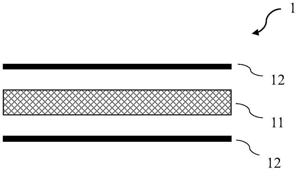
[0083] Get PTFE dispersion liquid (PTFE solid content 60% by weight) 666.67 grams and SiO 2 600 grams of fillers were evenly mixed to form the first glue (that is, in the solid content of the glue, the fillers accounted for 60% by weight). The first glue is further stirred to form a dough-like (dough-like), and extruded to obtain a sheet-like material, which is dried to remove the moisture and surfactant originally present in the PTFE dispersion, and then heated at a high temperature of 360°C Baking was performed to obtain a PTFE dielectric layer (first dielectric layer) not containing reinforcing cloth.

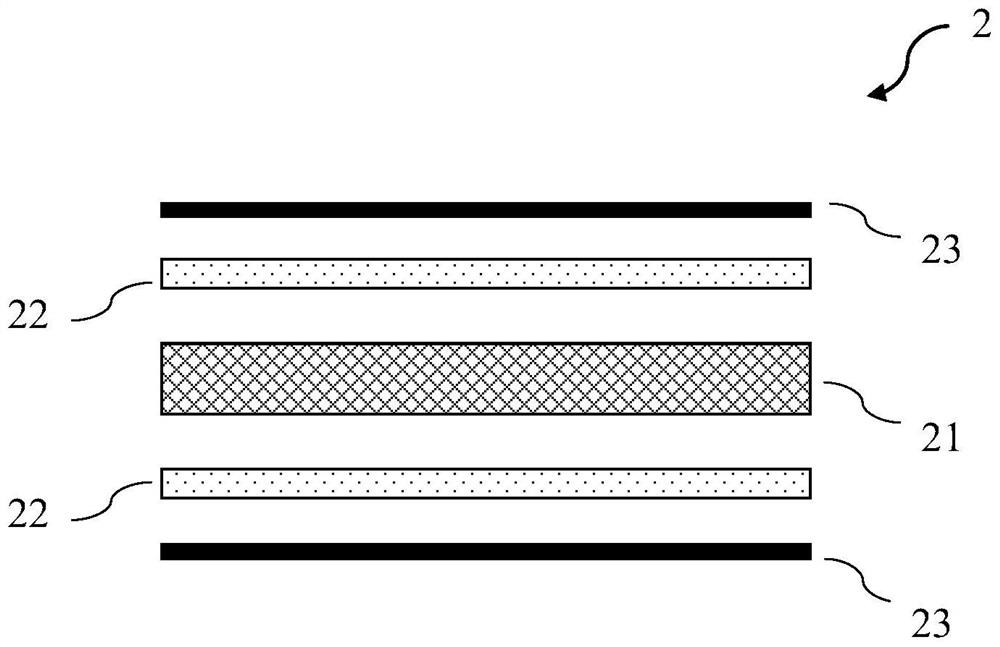
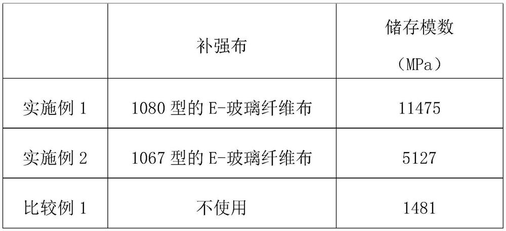
[0084] In addition, get 1333.33 grams of PTFE dispersion liquid (PTFE solid content 60% by weight) and SiO 2 200 grams of fillers were evenly mixed to form the second glue (that is, in the solid content of the glue, the fillers accounted for 20% by weight). The 1080 type E-glass fiber cloth (thickness 64 microns) was impregnated with the second glue, impregnated twice to a...

Embodiment 2

[0087] Get PTFE dispersion liquid (PTFE solid content 60% by weight) 666.67 grams and SiO 2 600 grams of fillers were evenly mixed to form the first glue (that is, in the solid content of the glue, the fillers accounted for 60% by weight). The first glue is further stirred to form a dough-like (dough-like), and extruded to obtain a sheet-like material, which is dried to remove the moisture and surfactant originally present in the PTFE dispersion, and then heated at a high temperature of 360°C Baking was performed to obtain a PTFE dielectric layer (first dielectric layer) not containing reinforcing cloth.

[0088] In addition, get 1333.33 grams of PTFE dispersion liquid (PTFE solid content 60% by weight) and SiO 2 200 grams of fillers were evenly mixed to form the second glue (that is, in the solid content of the glue, the fillers accounted for 20% by weight). The 1067-type E-glass fiber cloth (thickness 35 microns) is impregnated with the second glue, and impregnated twice t...


PUM

PropertyMeasurementUnit
thicknessaaaaaaaaaa
thicknessaaaaaaaaaa
melting pointaaaaaaaaaa

Abstract

The invention provides a metal foil laminated board, a printed circuit board applying the metal foil laminated board and a manufacturing method of the metal foil laminated board, and the metal foil laminated board comprises a first dielectric layer which includes first dielectric material and does not include reinforcing cloth, wherein the first dielectric material includes 20 wt% to 60 wt% of a first fluoropolymer and 40 wt% to 80 wt% of a first filler; a second dielectric layer which is arranged on at least one side of the first dielectric layer and comprises reinforcing cloth and a second dielectric material formed on the surface of the reinforcing cloth, the thickness of the reinforcing cloth is not larger than 65 micrometers, and the second dielectric material comprises 55%-100% by weight of second fluorine macromolecules and 0-45% by weight of second filler; and a metal foil which is arranged on the other side, opposite to the first dielectric layer, of the second dielectric layer.

Description

technical field [0001] The present invention relates to a metal foil laminate, in particular to a fluoropolymer metal foil laminate and a manufacturing method of the fluoropolymer metal foil laminate. The fluoropolymer metal foil laminate of the present invention is particularly suitable as a circuit substrate in the field of high-frequency technology, including radio frequency (RF) applications, microwave (microwave), millimeter wave (mmwave), antenna (antenna), radar (radar), etc. In the field of technology, it can especially meet the requirements of advanced materials for advanced applications such as fifth-generation mobile communications (5G), advanced driver assistance systems (ADAS), and artificial intelligence (AI). Background technique [0002] As the application of electronic products gradually develops towards high frequency, high speed, miniaturization of electronic components, and high density of substrate circuits, the requirements for the physical and chemical...

Claims


Application Information

Patent Timeline
Patent Type & Authority Applications(China)
IPC IPC(8): B32B27/20B32B27/32B32B17/02B32B15/20B32B15/14B32B17/06B32B15/085B32B27/06B32B27/34B32B27/02B32B27/36B32B27/12B32B33/00B32B37/10B32B37/06C08L27/18C08K3/36C08K7/14H05K1/03
CPCB32B27/20B32B27/322B32B5/02B32B15/20B32B15/14B32B17/061B32B15/085B32B27/06B32B27/12B32B33/00B32B37/10B32B37/06C08K3/36C08K7/14H05K1/036B32B2457/08B32B2262/101B32B2262/0261B32B2262/0253B32B2262/0276C08L27/18B32B5/024B32B2307/732B32B2307/204B32B2262/0269B32B27/285B32B5/022B32B2260/046B32B2264/10B32B2270/00B32B15/18B32B2250/40B32B2264/104B32B2264/101B32B2260/021B32B2264/108B32B2264/107B32B2264/12B32B2250/05B32B2264/102B32B27/304H05K1/0366H05K1/0373H05K2201/015H05K3/022H05K2201/0209H05K2201/026H05K2201/0257H05K2201/0191H05K2201/0195
Inventor 黄仕颖刘淑芬林楷翔
Owner TAIWAN POWDER TECH CO LTD
Features
  • R&D
  • Intellectual Property
  • Life Sciences
  • Materials
  • Tech Scout
  • Unparalleled Data Quality
  • Higher Quality Content
  • 60% Fewer Hallucinations
Learn More