Vehicle fan heater motor

A heater and motor technology, applied in the direction of electromechanical devices, electric components, electrical components, etc., can solve the problems of poor sealing, low room temperature, cumbersome operation, etc., and achieve the effect of accelerating the rate of air temperature rise and air flow

Pending Publication Date: 2021-03-05
肇庆市永智机械设备有限公司
View PDF0 Cites 0 Cited by
  • Summary
  • Abstract
  • Description
  • Claims
  • Application Information

AI Technical Summary

Problems solved by technology

[0002] At present, transport vehicles, farm vehicles, tractors, etc. are not well sealed, and the room temperature inside the vehicle is very low in winter, which brings great inconvenience to driving.
The existing solution is to use a heater, use circulating hot water or exhaust hot air to heat and heat, but its disadvantages are complex structure, cumbersome operation, high failure rate, and high manufacturing cost, which increases the burden on consumers

Method used


Image

  • Vehicle fan heater motor
  • Vehicle fan heater motor
  • Vehicle fan heater motor

Examples


Embodiment 1

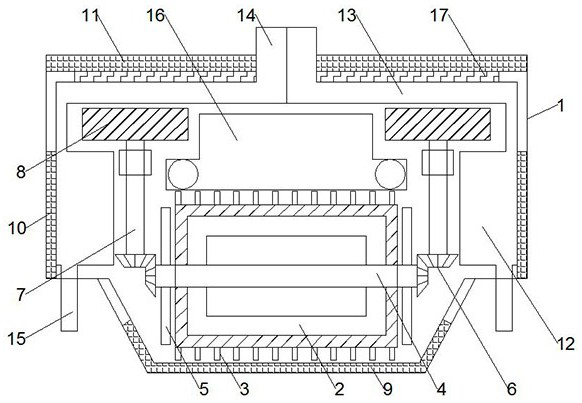
[0021] see figure 1 , in an embodiment of the present invention, a heater motor for a vehicle includes an outer cover 1, a horizontal motor 2 is arranged inside the outer cover 1, a rotating shaft-4 is arranged inside the motor 2, and the outer side of the motor 2 is along the direction of the rotating shaft-4. The axial direction is provided with cooling fins 3, and the left and right ends of the rotating shaft-4 are provided with fan-blades-5. The fan-blades-5 are composed of a disc-shaped whole, and several slits are arranged symmetrically in the center of the middle. Rotate along the direction of rotating shaft one 4, the air on both sides of fan blade one 5 is formed into an air flow, and the air flow is accelerated. The bevel gear set 6 is connected with the rotating shaft 2 7, and the upper end of the rotating shaft 7 7 is connected with the fan blade 2 8, and the rotating shaft 2 7 is rotatably connected in the outer cover 1, and the lower side of the motor 2 is provid...

Embodiment 2

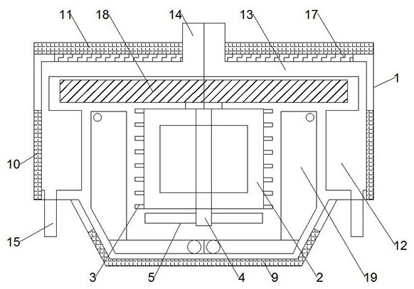
[0023] see figure 2 The difference between the present embodiment and the first embodiment is that: the outer cover 1 is provided with a vertical motor 2, the motor 2 is provided with a rotating shaft 4, and the outer side of the motor 2 is provided with a cooling fin 3 along the axial direction of the rotating shaft 4. , the lower end of the rotating shaft one 4 is provided with a fan blade one 5, the upper end of the rotating shaft one 4 is connected with a fan blade three 18, the left and right sides and the lower side of the motor 2 are provided with a condensation pipe two 19, and the condensation pipe Two 19 are connected to the refrigeration system in the car, and the air flow is driven by the fan blade three 18, and the heat in the hot water pipe is discharged into the car through the ventilation mesh three 11 by heat transfer.

[0024] The working principle of the present invention is: when in use, the hot water of the engine is transported through the thermal serpen...


PUM


Abstract

The invention discloses a vehicle fan heater motor, which comprises an outer cover, wherein a transverse motor is arranged in the outer cover, a first rotating shaft is arranged in the motor, coolingfins are arranged on the outer side of the motor in the axis direction of the first rotating shaft, first fan blades are arranged at the left end and the right end of the first rotating shaft, each first fan blade is composed of a disc-shaped whole, a plurality of gaps are symmetrically formed in the center of the middle and rotate in the direction of the first rotating shaft, air on the two sidesof the first fan blades forms airflow to accelerate air flowing, and the end of the first rotating shaft is connected with a bevel gear set. According to the invention, air in the outer cover is fully mobilized through air inlets and air outlets which are reasonably distributed, and the fan blades are driven by the motor to rotate, so that air flow can be accelerated while heat dissipation is performed on the motor; and auxiliary heating is performed by using the heating wires so that the indoor air temperature rise rate can be accelerated.

Description

technical field [0001] The invention relates to the technical field of vehicle air conditioning, in particular to a vehicle heater motor. Background technique [0002] At present, transport vehicles, agricultural vehicles, tractors, etc., are not well sealed, and the room temperature inside the vehicle is very low in winter, which brings great inconvenience to driving. The existing solution is to use a warm air blower and use circulating hot water or exhaust hot air to heat and heat, but its disadvantages are complex structure, cumbersome operation, high failure rate, and high manufacturing cost, which increases the burden on consumers. Therefore, those skilled in the art provide a vehicle heater motor to solve the problems raised in the background art above. Contents of the invention [0003] The object of the present invention is to provide a heater motor for a vehicle to solve the problems raised in the above-mentioned background technology. [0004] To achieve the ab...

Claims


Application Information

Patent Timeline
Patent Type & Authority Applications(China)
IPC IPC(8): B60H1/00B60H1/22H02K9/06
CPCB60H1/00357B60H1/00428B60H1/00457B60H1/00507B60H1/2215B60H2001/00614H02K9/06Y02T10/88
Inventor 黎顺展陆思如
Owner 肇庆市永智机械设备有限公司
Why Eureka
Try Eureka