Cyclone generator

A technology of swirl generator and discharge hole, which is applied in wellbore/well components, earthwork drilling, sealing/isolation, etc. It can solve the problem of insufficient displacement of the lower casing string, limited ability to replace drilling fluid, and Concave-convex and uneven problems, to achieve the effect of improving mechanical efficiency, facilitating large-scale promotion and use, and high initial speed

Pending Publication Date: 2021-03-05
中石化石油工程技术服务有限公司 +2
View PDF2 Cites 0 Cited by
  • Summary
  • Abstract
  • Description
  • Claims
  • Application Information

AI Technical Summary

Problems solved by technology

During the cementing process, when the casing is run into the wellbore, the cement slurry is injected from the casing mouth, and returns from the bottom of the casing to enter the annular space between the casing and the well wall. With the continuous injection of the cement slurry, the cement The slurry displaces the drilling fluid in the annulus out of the wellbore. The traditional method is one-dimensional axial flow displacement. The disadvantages of the conventional method are: (1) The flow velocity in the annulus near the wellbore wall is low, and the drilling fluid has a high viscosity. Adhesion, high adhesion requires high flow rate displacement, high flow rate

Method used


Image

  • Cyclone generator
  • Cyclone generator

Examples


Embodiment 1

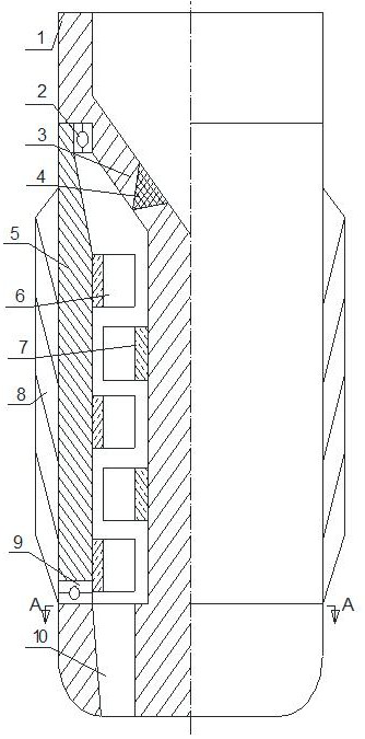
[0030] A swirl generator, comprising a central shaft 1, a one-way valve 4, an outer casing 5, a rotor 6, a stator 7, and a guide body 8; The through hole 3 is provided with a discharge hole 10 at the lower part of the central axis 1 . The outer casing 5 is wrapped on the annular groove of the central shaft 1, and forms a rotational fit with the central shaft 1. An annular driving chamber is formed between the outer casing 5 and the central shaft 1, and the upper and lower sides of the annular driving chamber respectively communicate with the bypass The hole 3 and the discharge hole 10 are connected. here combined with figure 1 , The center shaft 1 with the annular groove part of the axis is a closed structure to ensure that the fluid can only flow along the bypass hole 3, the annular drive chamber to the discharge hole 10. The one-way valve 4 is arranged in the bypass hole to prevent the fluid from flowing backward. The rotor 6 and the stator 7 are arranged between the oute...

Embodiment 2

[0032] On the basis of embodiment 1, further include:

[0033] A bearing A2 is mounted on the upper part of the outer casing 5 and the central shaft 1 , and a bearing B9 is installed on the lower part of the outer casing 5 and the central shaft 1 .

[0034] The bearing A2 is mounted on the radial junction of the outer casing 5 and the central shaft 1 , and the bearing B9 is installed on the axial junction of the outer casing 5 and the central shaft 1 .

[0035] Bearing A is a rolling bearing, and bearing B is a thrust bearing.

Embodiment 3

[0037] On the basis of embodiment 1 or 2, further include:

[0038] The upper section of the outer annular groove of the central shaft 1 is a tapered or arc-shaped surface, and the bypass hole 3 is arranged on the tapered or arc-shaped surface. This design better solves the force of the fluid on the rotor.

[0039] The bottom of the outer annular groove of the central shaft 1 is a plane, and the discharge hole 10 is arranged axially along the annular drive chamber between the outer shell 5 and the central shaft 1 to increase the smoothness of the flow channel.

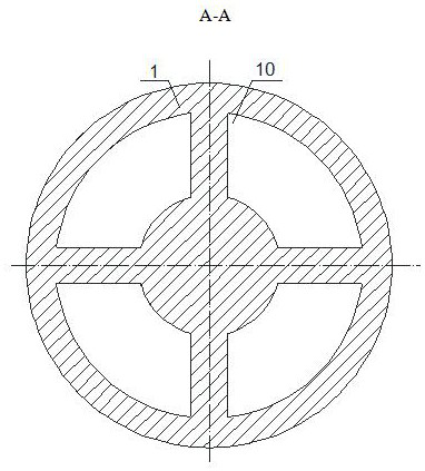
[0040] There are multiple bypass holes 3, which are determined according to factors such as hole diameter, fluid flow rate, casing pipe diameter, pressure, etc., and are uniformly distributed.

[0041] There are multiple discharge holes 10, the number and diameter of which are specifically set according to requirements, and are uniformly distributed; or the discharge holes 10 directly adopt an integral annular structure...


PUM


Abstract

The invention discloses a cyclone generator which is mainly composed of a center shaft, a one-way valve, an outer shell, a rotor, a stator and a flow guide body. An annular groove is formed in the periphery of the center shaft; a bypass hole is formed in the upper portion of the center shaft; a flow drainage hole is formed in the lower portion of the center shaft; the outer shell wraps the annulargroove of the center shaft and is in rotating fit with the center shaft; an annular driving cavity is formed between the outer shell and the center shaft; the upper portion and the lower portion of the annular driving cavity are communicated with the bypass hole and the flow drainage hole respectively; the one-way valve is arranged in the bypass hole; the rotor and the stator are arranged in theannular driving cavity formed between the outer shell and the center shaft; the rotor is fixed to the inner wall of the outer shell; the stator is fixed to the outer wall of the center shaft; and theflow guide body is arranged on the outer surface of the outer shell. The cyclone generator can completely meet the well cementation process requirements of complex structure wells of domestic verticalwells, directional wells and horizontal wells, and is a novel tool which is simple in structure, convenient to operate, low in cost, safe and reliable.

Description

technical field [0001] The invention relates to a downhole tool in the fields of oil and gas drilling, coal bed methane drilling, geological exploration, mine drilling, etc., in particular to a swirl generator. Background technique [0002] After the drilling and completion operation is completed, in order to ensure the stability of the wellbore and the safety and smoothness of subsequent construction operations, casings must be run in the wellbore, and cement should be injected into the annular space between the casing and the well wall. After the cement solidifies, a stable wellbore is formed. During the cementing process, when the casing is run into the wellbore, the cement slurry is injected from the casing mouth, and returns from the bottom of the casing to enter the annular space between the casing and the well wall. With the continuous injection of the cement slurry, the cement The slurry displaces the drilling fluid in the annulus out of the wellbore. The traditiona...

Claims


Application Information

Patent Timeline
IPC IPC(8): E21B33/13
CPCE21B33/13
Inventor 李文飞周延军李子杰赵波韩忠文曹向峰肖新磊梁明月李涛程国强
Owner 中石化石油工程技术服务有限公司
Why Eureka
Try Eureka