Air-driven ducted fan jet propulsion power system

A ducted fan, jet propulsion technology, applied in jet propulsion devices, machines/engines, liquid fuel engines, etc., can solve the problems of complex mechanical mechanism, limited load, high fuel consumption, etc., to achieve reduced flow separation, high power The effect of output, low fuel consumption

Active Publication Date: 2022-04-05
NANJING UNIV OF AERONAUTICS & ASTRONAUTICS
View PDF6 Cites 0 Cited by
  • Summary
  • Abstract
  • Description
  • Claims
  • Application Information

AI Technical Summary

Problems solved by technology

[0004] The present invention provides a drive ducted fan jet propulsion power system capable of achieving high thrust and low fuel consumption, which can effectively solve the problem of complex mechanical mechanism of the power system of the aircraft proposed in the above background technology, resulting in greatly limited load and high fuel consumption.

Method used


Image

  • Air-driven ducted fan jet propulsion power system
  • Air-driven ducted fan jet propulsion power system
  • Air-driven ducted fan jet propulsion power system

Examples


Embodiment Construction

[0025] The preferred embodiments of the present invention will be described below in conjunction with the accompanying drawings. It should be understood that the preferred embodiments described here are only used to illustrate and explain the present invention, and are not intended to limit the present invention.

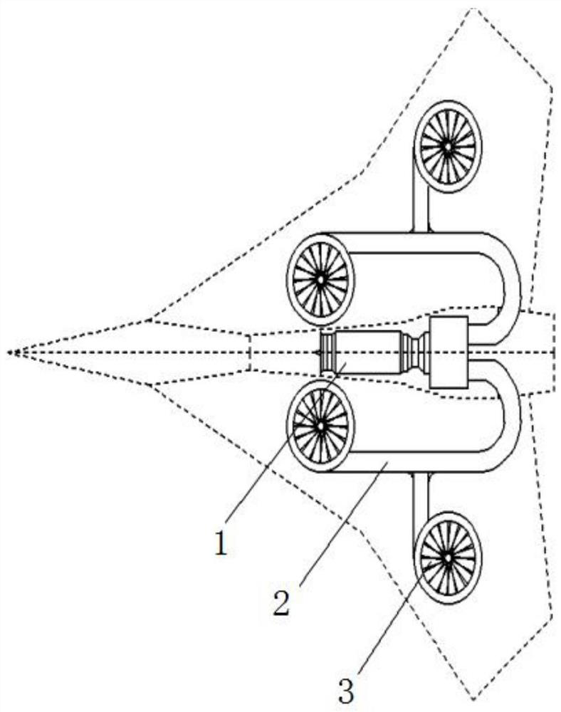
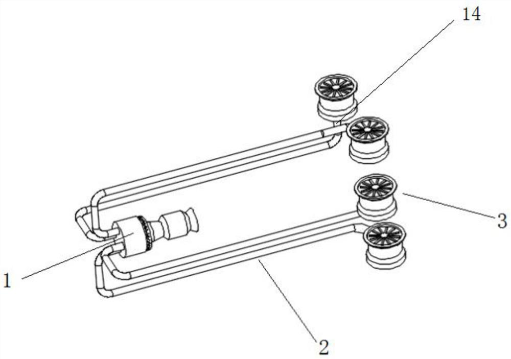
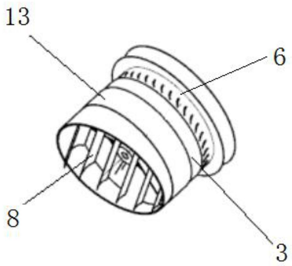
[0026] Example: such as Figure 1-4 As shown, a gas-driven ducted fan jet propulsion system includes a core turbine 1, a ducted fan 3 connected to the core turbine 1 through an air induction pipe 2, and a tip turbine 6 coaxially installed with the ducted fan 3, the core Turbine 1 discharges high-energy gas, which is transported through the freely arranged air-inducing pipe 2, wherein the air-inducing pipe 2 is installed with a throttle valve for adjusting the air flow, so as to adjust the air flow entering the ducted fan 3, so as to realize the pushing size of the ducted fan 3 The ducted fan 3 includes an intake volute 4 connected to the blade tip turbine 6 and a ro...


PUM


Abstract

The invention discloses an air-driven ducted fan jet propulsion power system, comprising a core turbine, a ducted fan connected to the core turbine through an air induction pipe, and a blade tip turbine coaxially installed with the ducted fan, the core turbine exhausts gas It is transmitted to the blade tip turbine, and the blade tip turbine works on the expansion of the gas, driving the bypass fan to rotate and inhale the air to generate thrust, which breaks through the design limitation of conventional turbofan engines with large bypass ratio, greatly increases the bypass ratio of the engine, and further exerts its large capacity. The basic principle of bypass ratio turbofan engine to improve propulsion efficiency, lower fuel consumption and higher power output, and the function of the induction pipe connected between the energy source core turbine and the bypass fan is only the airflow channel without complicated machinery The connection can be arranged inside the fuselage and wings according to the design needs of the aircraft, giving the aircraft a more flexible layout.

Description

technical field [0001] The invention relates to the technical field of aircraft power, in particular to an air-driven ducted fan jet propulsion power system. Background technique [0002] Straight take-off and landing technology is a technology that has emerged since the 1950s and 1960s. This technology can help fixed-wing aircraft reduce or basically get rid of their dependence on runways, and only need a small flat ground to achieve fast and safe take-off and landing. Therefore, aircraft with vertical take-off and landing capabilities do not require special airports and runways, and are highly adaptable to terrain. They can be distributed or equipped on ships, which is convenient for flexible attacks, transfers, camouflage and concealment, and can complete other fixed operations such as hovering in the air. High-difficulty actions that cannot be completed by wing aircraft; with the innovation of foreign vertical take-off and landing aircraft concepts, the most important te...

Claims


Application Information

Patent Timeline
Patent Type & Authority Patents(China)
IPC IPC(8): F02K3/00F02K3/12F04D29/54F04D29/56F04D27/00
CPCF02K3/00F02K3/12F04D29/541F04D29/542F04D29/563F04D27/002
Inventor 黄国平周扬朱远昭夏晨
Owner NANJING UNIV OF AERONAUTICS & ASTRONAUTICS
Why Eureka
Try Eureka