
Conveying belt type source separation pedestal pan

A conveyor belt and toilet technology, which is applied in the field of public health appliances, can solve the problems of odor pollution, poor use effect, burst or overflow, etc., and achieves the effect of saving water resources and preventing the breeding of mosquitoes and flies.

Pending Publication Date: 2021-03-09
TONGJI UNIV
View PDF6 Cites 1 Cited by
  • Summary
  • Abstract
  • Description
  • Claims
  • Application Information

AI Technical Summary

Problems solved by technology

This method still needs water, and it is easy to cause discomfort to the toilet users
[0005] 3) Foam-blocked toilets, but the use of toilets with low frequency will cause the foam to evaporate quickly, causing odor pollution after the water seal disappears. In addition, the manure mixed with foam will bring some waste to the biological sewage treatment plant. Deal with hidden dangers
But the cost of this closet and operating cost are higher
[0007] 5) Packed and sealed toilets, the packed bag packs and seals the feces and dirt into the feces storage box, and then sends them to the follow-up treatment site for unified and harmless treatment, but the packed feces need to be transported twice, and the secondary treatment will increase Reduced transportation costs; it is inevitable that bursts or overflows will occur during stacking and transportation of manure bags, resulting in secondary pollution
[0008] The above toilets often make the toilet user feel uncomfortable during use, and cannot effectively remove the odor, and cannot keep the toilet clean. In the case of complete anhydrous, the use effect is poor

Method used


Image

  • Conveying belt type source separation pedestal pan
  • Conveying belt type source separation pedestal pan

Examples


Embodiment Construction

[0021] Specific embodiments of the present invention will be described in detail below in conjunction with the accompanying drawings.

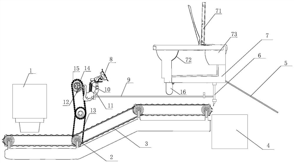
[0022] like figure 1 As shown, the conveyor-type source separation toilet of the present invention includes a support frame (not shown in the figure), a toilet 7, a conveyor belt assembly, an ash storage box 1, a feces box 4, a urine storage barrel, and a pedal mechanism; wherein the toilet 7 A partition 72 is set in the middle to divide it into a urine urinal and a cesspool to collect urine and feces respectively. In addition, a baffle 71 can also be set on the top of the toilet to divide the cesspool again, and embed the urine collection in the cesspool. Cavity 73 is used for man standing to urinate. The urine collection cavity is communicated with the pipeline 16, and the bottom of the urinal is provided with a urination outlet and connected to the urine storage bucket (not shown in the urine storage bucket figure) through the pipeline 16. ...


PUM


Abstract

The invention discloses a conveying belt type source separation pedestal pan which comprises a supporting frame, a pedestal pan body, a conveying belt assembly, an ash storage box, a manure box, a urine storage barrel and a pedal mechanism. A partition plate is arranged in the pedestal pan to divide the pedestal pan into a urinal and an excrement pool, the conveying belt assembly comprises a conveying belt and rollers, the rollers are used for driving the conveying belt to rotate, the ash storage box and the excrement box are located at the two ends of the conveying belt respectively, the ashstorage box is located above the conveying belt, an ash discharging opening is formed in the bottom of the ash storage box, and the distance between the ash discharging opening and the conveying beltis 1-3 cm. The blocking door is located below the pedestal pan, can rotate so as to be opened and closed, and is used for blocking gas flow between the closestool and the excrement box when being closed. When the toilet stool is in a use state, the blocking door blocks the contact between the excrement box and a user, the upward escape of odor is inhibited, meanwhile, ash materials such as wood chips and plant ash further adsorb the odor of excrement, no mosquitoes and flies breed, and the toilet stool is clean and sanitary.

Description

technical field [0001] The invention relates to the field of public health appliances, in particular to a novel conveyor belt type source separation toilet technology. Background technique [0002] At present, the common toilets for changing toilets are water-flush toilets or squatting toilets, which adopt water-sealed deodorization, and water-flush toilets waste a lot of water. Many anhydrous or water-saving toilets have appeared in the market, but they have not been effectively promoted. The specific types are as follows: [0003] 1) Urine flushing treatment technology, by adding a deodorizing, sterilizing, disinfecting, lubricating and anti-scaling agent or bacterial solution to treat the urine collected separately, and produce a new type of environmentally friendly flushing liquid that can be used to flush toilets; After the stool is mixed with the flushing liquid, it becomes an odorless thick slurry through stirring, elutriation and other processes, and the thick slurr...

Claims


Application Information

Patent Timeline
IPC IPC(8): A47K11/03C02F11/00C02F11/12
CPCA47K11/03C02F11/00C02F11/12C02F2303/02Y02A50/30
Inventor 周雪飞张亚雷尤慰先尹文俊陈家斌徐悦高峰
Owner TONGJI UNIV
Learn More