
Vertical machining stamping equipment

A technology of machining and punching equipment, applied in the field of punching, can solve the problems of cumbersome punching, and achieve the effect of accurate punching position and not easy to deform

Inactive Publication Date: 2021-03-09
盐城市科瑞达科技咨询服务有限公司
View PDF0 Cites 3 Cited by
  • Summary
  • Abstract
  • Description
  • Claims
  • Application Information

AI Technical Summary

Problems solved by technology

[0003] 1. When the workpiece is stamped, it needs to be fixed with the corresponding stamping fixture. When the steel pipe needs to be punched, it needs to be fixed and then stamped. When the four end faces of the steel pipe need to be punched, it needs to be manually Turn the steel pipe over, and then fix the steel pipe before stamping. Such stamping steps make stamping more cumbersome;

Method used


Image

  • Vertical machining stamping equipment
  • Vertical machining stamping equipment
  • Vertical machining stamping equipment

Examples


Embodiment Construction

[0033] The embodiments of the present invention will be described in detail below with reference to the accompanying drawings, but the present invention can be implemented in many different ways as defined and covered by the claims.

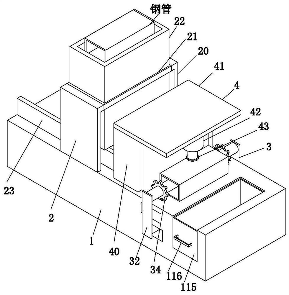
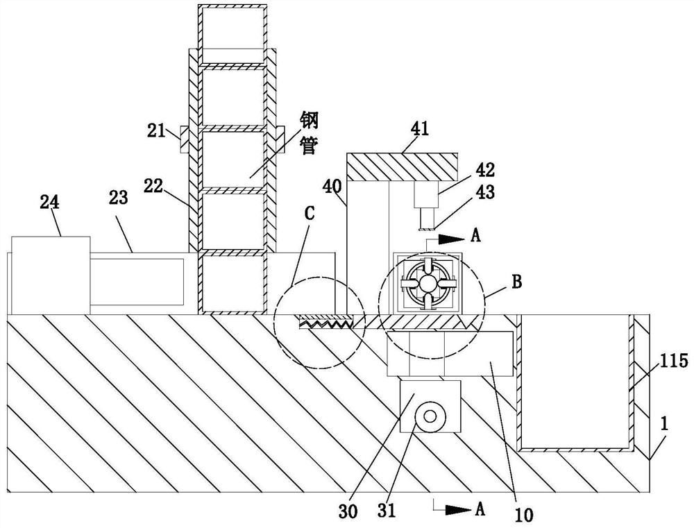
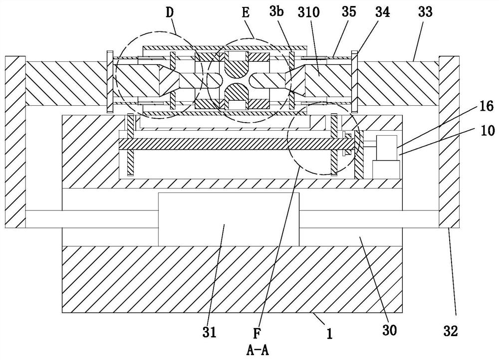
[0034] Such as Figure 1 to Figure 11 As shown, a vertical machining stamping equipment includes a workbench 1, a moving mechanism 2, a fixing mechanism 3 and a stamping mechanism 4. The upper end surface of the workbench 1 is equipped with a moving mechanism 2 on the left side, and the workbench 1 A fixing mechanism 3 is installed on the right side of the upper end surface, and a stamping mechanism 4 is arranged between the fixing mechanism 3 and the moving mechanism 2 .

[0035] The front end of the workbench 1 is provided with a mounting groove 10, the mounting groove 10 is located above the rectangular slot 30, the mounting groove 10 is equipped with a vertical plate 11 near the left side of the front end, and the vertical plate 11 and the mo...


PUM


Abstract

The invention relates to vertical machining stamping equipment. The vertical machining stamping equipment comprises a workbench, a moving mechanism, a fixing mechanism and a stamping mechanism, wherein the moving mechanism is installed on the left side of the upper end surface of the workbench, the fixing mechanism is installed on the right side of the upper end surface of the workbench, and the stamping mechanism is arranged between the fixing mechanism and the moving mechanism. According to the vertical machining stamping equipment, when a steel pipe is fixed by the fixing mechanism, the inside of the steel pipe can be supported, so that the steel pipe has supporting force during stamping, and the deformation of the steel pipe is not prone to being caused; meanwhile, the fixing mechanismcan further turn over the steel pipe, so that multi-end-surface punching of the steel pipe is facilitated, the use effect of multiple purposes of one machine is achieved, and the punching position ofthe steel pipe is more accurate; and a moving plate moves when the steel pipe is turned over, so that the steel pipe moves without resistance, and the steel pipe is reset under the action of a supporting spring after being turned over so as to support the lower end of the steel pipe.

Description

technical field [0001] The invention relates to the technical field of stamping, in particular to a vertical machining stamping equipment. Background technique [0002] Stamping is to rely on presses and molds to apply external force to plates, strips, pipes and profiles, etc., to cause plastic deformation or separation, so as to obtain workpieces (stamping parts) of required shape and size. Forming processing method, sheet material, mold And equipment are the three elements of stamping processing. According to the stamping processing temperature, it is divided into hot stamping and cold stamping. The former is suitable for sheet metal processing with high deformation resistance and poor plasticity; the latter is carried out at room temperature and is a commonly used stamping method for thin plates. It is one of the main methods of metal plastic processing (or pressure processing), and it also belongs to material forming engineering technology. The mold used for stamping is ...

Claims


Application Information

Patent Timeline
Patent Type & Authority Applications(China)
IPC IPC(8): B21D28/34B21D28/28B21D43/00B21D43/14B21D43/16B21D43/02B21D43/20B21D45/04
CPCB21D28/28B21D28/34B21D43/003B21D43/026B21D43/027B21D43/145B21D43/16B21D43/20B21D45/04
Inventor 张键王斌周临震侍正存
Owner 盐城市科瑞达科技咨询服务有限公司
Learn More