
Automatically-feeding shielding case die

A technology of automatic material feeding and shielding cover, which is applied in the direction of forming tools, manufacturing tools, feeding devices, etc. It can solve problems such as scratches, adhesion and difficulty of separation, and the influence of shielding cover production yield, so as to improve the yield rate and improve processing efficiency , to avoid the effect of scratching each other

Pending Publication Date: 2021-03-09
成都市普瑞昇科技有限公司
View PDF6 Cites 0 Cited by
  • Summary
  • Abstract
  • Description
  • Claims
  • Application Information

AI Technical Summary

Problems solved by technology

[0008] 1. When the existing shielding covers are cleaned during the production process, each shielding cover is separated, and the collision and abrasion between each other are more serious
[0009] 2. When the existing shielding cover is cleaned during the production process, once the planes between the shielding covers overlap, they will stick together, because there is oil stains between the planes, and the adhesion is difficult to separate, resulting in the shielding cover when the oil stain is cleaned. Cleaning is not clean, adhesion and oil pollution have a serious impact on the subsequent production and yield of the shielding cover

Method used


Image

  • Automatically-feeding shielding case die
  • Automatically-feeding shielding case die
  • Automatically-feeding shielding case die

Examples


Embodiment 1

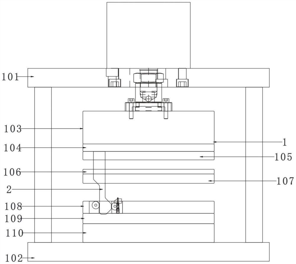
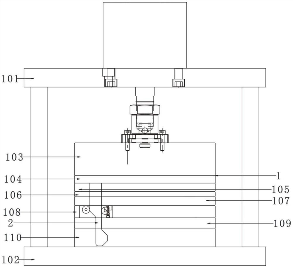
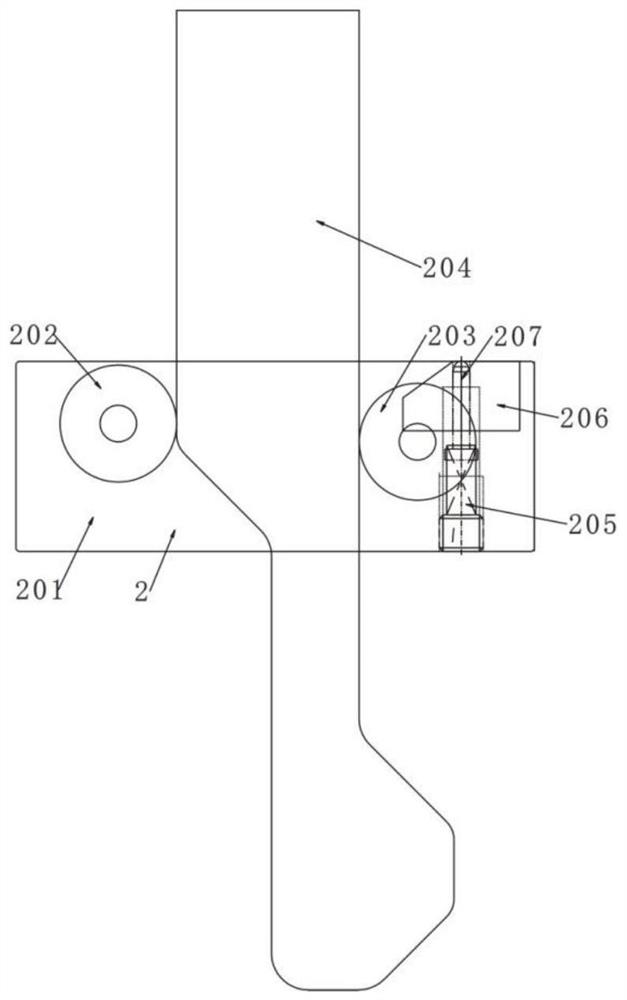
[0038] like figure 1 figure 2 image 3 As shown, an automatic feeding shielding mold, the mold includes an upper mold base, an upper backing plate, a fixed plate, a limit plate, a discharge plate, a concave plate, a lower backing plate, and a lower mold base, and the plates of the mold are stacked in sequence Installation, the inside of the mold is provided with an automatic feeding mechanism, and the automatic feeding mechanism includes a slider 201, a bearing, a movable block 206, a thimble 207, a spring 205, and a pull rod 204. Bearings are arranged on both sides of the pull rod 204 groove, a groove is arranged at the front end of the slider 201, a movable block 206 is arranged in the groove, a thimble hole is arranged on the movable block 206, a thimble 207 is arranged in the thimble hole, and a thimble 207 is provided at the bottom The spring 205, the upper end of the pull rod 204 are fixed on the upper backing plate 104 of the mold, the slider 201 is slidably installe...


PUM


Abstract

The invention discloses an automatically-feeding shielding case die. An automatic feeding mechanism is arranged in the die and comprises a sliding block, bearings, a movable block, an ejector pin, a spring and a pull rod; a pull rod groove is formed in the middle part of the sliding block; the pull rod is arranged in the pull rod groove; the bearings are arranged at the two sides of the pull rod groove; a groove is formed in the front end of the sliding block; the movable block is arranged in the groove; an ejector pin hole is formed in the movable block; the ejector pin is arranged in the ejector pin hole; the spring is arranged on the lower part of the ejector pin; the upper end of the pull rod is fixed to an upper base plate of the die; the sliding block is slidably installed on a female die plate of the die; a material belt is installed on the automatic feeding mechanism; and equidistant material belt holes are correspondingly formed in the two side edges of the material belt. Automatic loading for the shielding cases can be realized, so that the machining efficiency is increased, and scratching between the shielding cases during loading and conveying is avoided; and meanwhilethe special material belt is arranged to avoid adhesion, oil contamination and scratching during cleaning. Great increasing for the yield is brought, and the yield is increased to 90% or above from original 80%.

Description

technical field [0001] The invention belongs to the technical field of shielding cover production, and in particular relates to an automatic feeding shielding cover mold. Background technique [0002] A shield is a tool used to shield electronic signals. The function is to shield the influence of external electromagnetic waves on the internal circuit and the external radiation of electromagnetic waves generated inside. Stainless steel and nickel nickel are mainly used as materials, of which nickel nickel is a metal shielding material that is easy to be tinned. [0003] The main function of the shielding cover is to block the electromagnetic wave in the cover, protect the internal electronic equipment from the harm of electromagnetic radiation, and avoid interference to other electrical appliances around it. life. There are two main functions of the shielding cover. The conscious shielding cover surrounds the interference source of components, circuits, assemblies, cables o...

Claims


Application Information

Patent Timeline
IPC IPC(8): B21D37/10B21D37/08B21D35/00B21D43/02B21D45/04B21D43/28
CPCB21D37/10B21D37/08B21D35/00B21D43/02B21D45/04B21D43/287
Inventor 卓越张微罗旭黄华富
Owner 成都市普瑞昇科技有限公司
Learn More