
Ladle automatic casting system and method
A casting system and ladle technology, applied in casting equipment, casting molten material containers, manufacturing tools, etc., can solve the problems of low service life, low production efficiency, harsh site environment, etc., to avoid high temperature operation, high positioning accuracy, and use Long life effect
- Summary
- Abstract
- Description
- Claims
- Application Information
AI Technical Summary
Problems solved by technology
Method used
Image

Examples
Embodiment Construction
[0023] The present invention will be further described below in conjunction with drawings and embodiments.
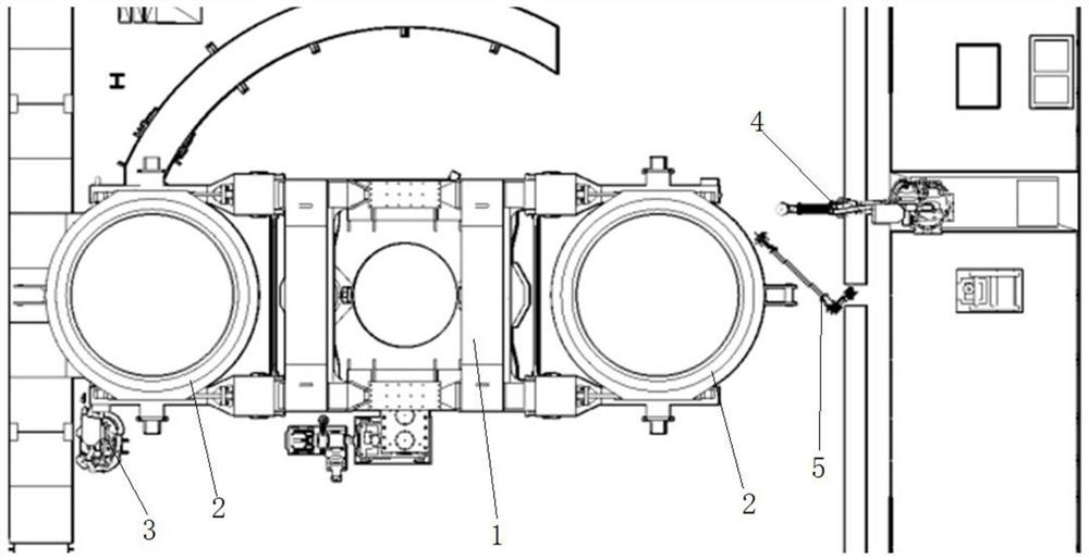
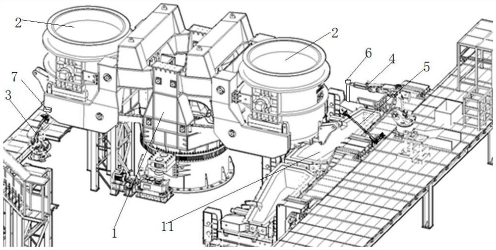
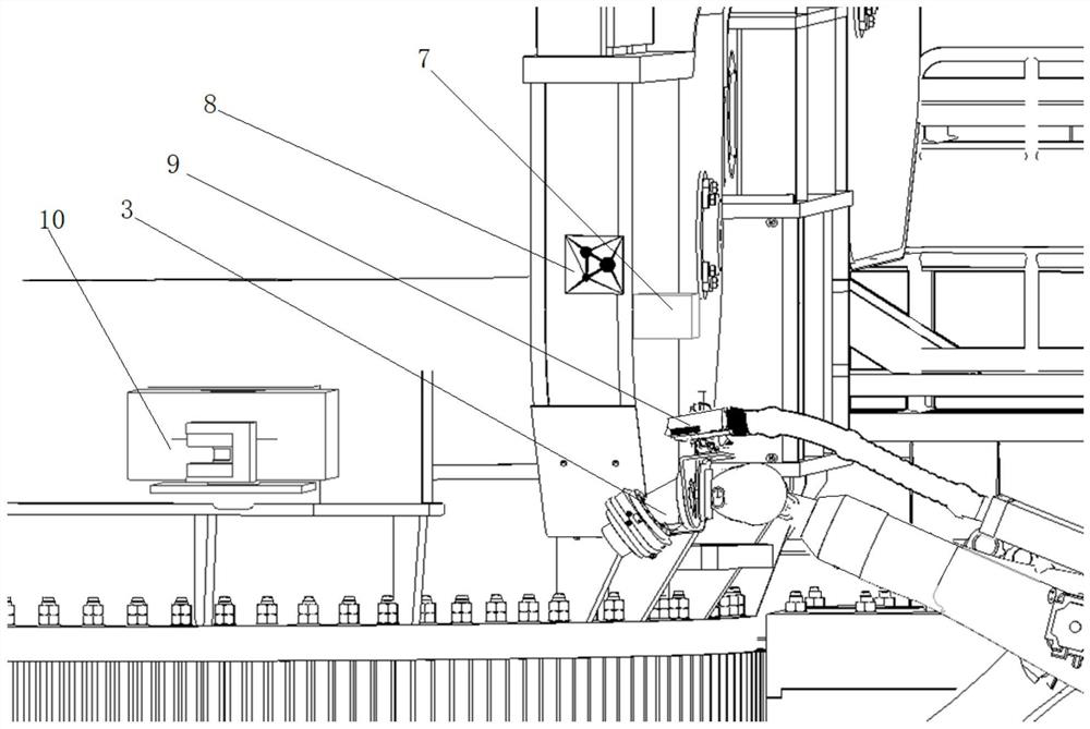
[0024] Such as Figure 1 to Figure 4 As shown, a ladle automatic casting system includes a positioning plate 8 fixed on the yoke of the turntable 1, a water inlet cylinder 7 placed on the yoke of the turntable 1, a steel pick-up robot 3 near the pick-up position, and a The casting position robot 4 and the collaborative manipulator 5 near the casting position are equipped with 3D scanners 9 on the steel position robot 3 and the casting position robot 4, and the collaborative manipulator arm 5 is driven up and down by the lifting device; the steel position robot 3 can drive the 3D scanner 9 to scan to obtain the coordinates of the positioning plate 8 and the nozzle mechanism 10 at the steel connection position and obtain the relative positional relationship between the two. The steel connection robot 3 can drive the 3D scanner 9 to scan to obtain the nozzle at the steel c...
PUM
 Abstract
Description
Claims
Application Information