Joint assembly of desktop mechanical arm, desktop mechanical arm and robot

A technology of robotic arms and joints, applied in the field of desktop robotic arms, can solve problems such as low safety, low connection strength of the arm body structure, coordination stability, and poor driving effect

Pending Publication Date: 2021-03-09
SHENZHEN YUEJIANG TECH CO LTD
View PDF11 Cites 22 Cited by
  • Summary
  • Abstract
  • Description
  • Claims
  • Application Information

AI Technical Summary

Problems solved by technology

[0003] At present, desktop manipulators are usually educational desktop manipulators, and the objects grasped by the end are light in weight and light in load. Therefore, there are no strict requirements for the structural design of the connection and cooperation between the joints of the big and small arms. For example, the application number is "A compact belt-driven enclosed small four-axis robot" disclosed in the Chinese patent CN201910723747.2 and "a compact belt-driven small four-axis robot" disclosed in the Chinese patent application number CN2018109211573.6, The driving rod of the forearm and the main rod of the forearm are connected through a single triangular connection to realize the transmission, and the boom is designed with a single rod structure; ...

Method used


Image

  • Joint assembly of desktop mechanical arm, desktop mechanical arm and robot
  • Joint assembly of desktop mechanical arm, desktop mechanical arm and robot
  • Joint assembly of desktop mechanical arm, desktop mechanical arm and robot

Examples


Embodiment Construction

[0035]The solutions in the embodiments of the present invention will be clearly and completely described below in conjunction with the accompanying drawings in the embodiments of the present invention. Apparently, the described embodiments are only some of the embodiments of the present invention, not all of them. Based on the embodiments of the present invention, all other embodiments obtained by persons of ordinary skill in the art without creative efforts fall within the protection scope of the present invention.

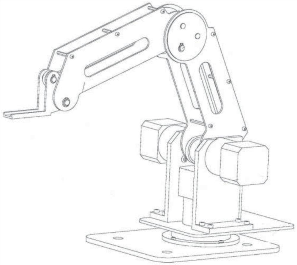
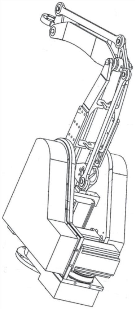
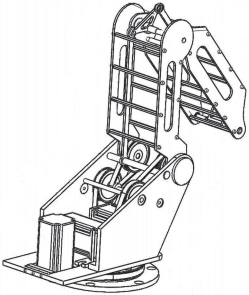
[0036] As a subcategory of robotic arms, the desktop robotic arm consists of a base, a turntable, a large arm, a small arm, a terminal, and a rotary table drive motor, a large arm drive motor, and a small arm drive motor. The rotary table and the base are rotatably connected. They are respectively connected to the turntable and the small arm, the small arm is connected to the end, the end is used to set the actuator, the turntable drive motor is used to drive the ...


PUM


Abstract

The invention discloses a joint assembly of a desktop mechanical arm. The joint assembly comprises a big arm, a forearm and two connecting pieces arranged between the big arm and the forearm; the bigarm comprises a big arm main rod and a big arm auxiliary rod which are oppositely arranged; the forearm comprises a forearm main rod and a forearm auxiliary rod which are oppositely arranged; the first end of the big arm main rod is provided with two first hinge parts which are oppositely arranged left and right at intervals; the two connecting pieces are arranged side by side and left and right and are located between the two first hinge parts; the first end of the forearm main rod is provided with a second hinge part; the second hinge part is located between the two connecting pieces; the two first hinge parts, the two connecting pieces and the second hinge part are connected through a first hinge shaft; and the first end of the big arm auxiliary rod and the first end of the forearm auxiliary rod are hinged to the two opposite sides of the two connecting pieces correspondingly. According to the joint assembly of the desktop mechanical arm, the connecting strength is enhanced, the matching stability and the driving effect are improved, the supporting strength is enhanced, and the safety is improved. In addition, the invention further discloses the desktop mechanical arm and a robot.

Description

technical field [0001] The invention relates to the technical field of desktop manipulators, in particular to a joint assembly of a desktop manipulator, a desktop manipulator and a robot. Background technique [0002] As a subcategory of robotic arms, the desktop robotic arm consists of a base, a turntable, a large arm, a small arm, a terminal, and a rotary table drive motor, a large arm drive motor, and a small arm drive motor. The rotary table and the base are rotatably connected. They are respectively connected to the turntable and the small arm, the small arm is connected to the end, the end is used to set the actuator, the turntable drive motor is used to drive the turntable to rotate relative to the base, the boom drive motor is used to drive the boom movement, and the small arm drive motor is used for To drive the movement of the forearm, the upper arm and the forearm use the principle of parallelogram to drive the end to move in the working space. For example, the a...

Claims


Application Information

Patent Timeline
IPC IPC(8): B25J17/00B25J9/12B25J9/10B25J9/06B25J18/00B25J19/00
CPCB25J17/00B25J9/126B25J9/10B25J9/06B25J18/00B25J19/00
Inventor 叶伟智李叶鹏王重彬刘培超刘主福王伦郎需林
Owner SHENZHEN YUEJIANG TECH CO LTD
Why Eureka
Try Eureka