Edge cutting equipment for food bag processing

A food bag and edge trimming technology, applied in packaging and other directions, can solve problems such as uneven trimming, affecting the trimming of food bags, and inability to clean up leftovers in time, and achieves the effects of avoiding damage, easy operation and wide application.

Inactive Publication Date: 2021-03-09
含山县贝亲生物科技有限公司
View PDF1 Cites 4 Cited by
  • Summary
  • Abstract
  • Description
  • Claims
  • Application Information

AI Technical Summary

Problems solved by technology

The device has high trimming efficiency, high trimming quality, and wide application range, but the invention still has the following deficiencies during use: the leftovers produced by trimming cannot be cleaned up in time, which will affect the trimming of the food bag behind; Lack of compression and fixation of the food bag, prone to the problem of irregular trimming due to the sliding of the food bag

Method used


Image

  • Edge cutting equipment for food bag processing
  • Edge cutting equipment for food bag processing
  • Edge cutting equipment for food bag processing

Examples


Embodiment 1

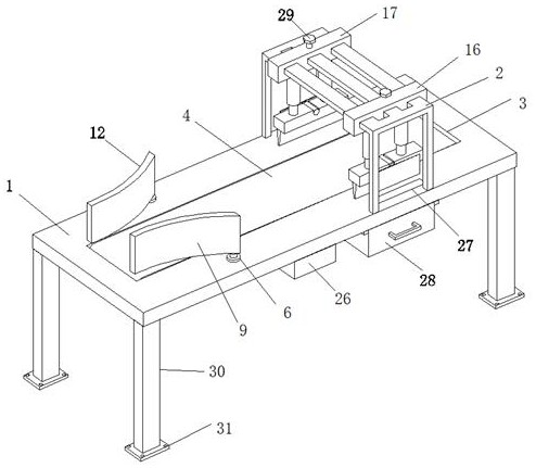
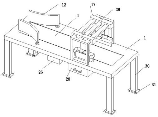
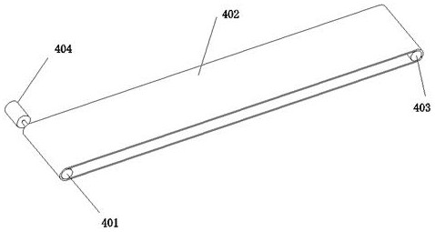
[0035] The working process of Embodiment 1 is as follows: firstly, the expansion and contraction of the first electric push rod 15 can be controlled to drive the double-sided rack 14 to move left or right, and then the first gear 10 and the second gear 13 can be driven by a pair of intermediate gears Simultaneously turn to the opposite direction, thereby the opening and closing angle between the front guide piece 9 and the rear guide piece 12 can be further adjusted; then a stack of plastic bags to be trimmed is placed on the conveyor belt 402 upper surface, and then the driving motor 404 is controlled to work The plastic bag is sent to the right below the frame 2; then the hydraulic cylinder 18 is controlled to drive the knife seat 19 and the blade 20 to move down and cut the food bag. The blade 20 just touches the surface of the workbench 1, and the proximity position sensor 24 will send two signals to the control box 26 on the lower end of the workbench 1. One signal can sto...

Embodiment 2

[0038] Embodiment 2 is on the basis of embodiment 1, as Figure 6 and Figure 7 As shown, the opposite sides of the two tool holders 19 are also fixed with a pressure bag assembly 5, the pressure bag assembly 5 includes a fixed plate 501, a return spring 502, a connecting rod 503 and a pressure plate 504, and the surface of the fixed plate 501 is equidistantly provided with A plurality of round holes 505, each round hole 505 is sleeved with a connecting rod 503, the top of the connecting rod 503 is fixed with a top cap 506, the bottom of the connecting rod 503 is fixed with a pressure plate 504; the return spring 502 is sleeved on the connecting rod 503 , and the return spring 502 is disposed between the lower surface of the fixing plate 501 and the upper surface of the pressing plate 504 .

[0039] Embodiment 2 When the blade 20 cuts the food bag, the pressing plate 504 will first touch the upper surface of the food bag, and as the knife seat 19 and the blade 20 continuously...


PUM


Abstract

The invention relates to the technical field of food bag edge cutting, in particular to edge cutting equipment for food bag processing. The edge cutting equipment comprises a workbench and a rack, a conveying groove is formed in the surface of the workbench, and a conveying assembly is installed in the conveying groove; a front bearing seat and a rear bearing seat are installed on the upper end face of the left half section of the workbench, a first rotating shaft is rotationally installed in the front bearing seat, a front guide piece is fixed to the top end of the first rotating shaft, a second rotating shaft is rotationally installed in the rear bearing seat, and a rear guide piece is fixed to the top end of the second rotating shaft; and a rack is fixed to the upper end face of the right half section of the workbench, a front moving base and a rear moving base are slidably installed on the rack, the bottom end of the front moving base and the bottom end of the rear moving base arefixedly connected to tool aprons through hydraulic cylinders, and blades are installed at the lower ends of the tool aprons. According to the edge cutting equipment, food bags with different widths can be conveniently guided in for edge cutting, operation is easy and convenient, and the application range is wide; and intelligent leftover material clearing can be realized.

Description

technical field [0001] The invention relates to the technical field of edge trimming of food bags, in particular to an edge trimming device for processing food bags. Background technique [0002] As we all know, food packaging bags and food preservation bags are collectively referred to as food bags. Food bags have good moisture-proof, mildew-proof, prevent food from hardening and drying, isolate oxygen, prevent food oxidation, and prolong food preservation. It can be said that people cannot live without food bags. The production of food bags generally adopts hot-press sealing. Before sealing, the bag surface needs to be trimmed to ensure neat and beautiful appearance after sealing. For example, the utility model of patent application No. CN201920060887.1 discloses a cutting method for snack packaging bags. The side device includes a bottom plate, a vertical plate and a top plate. Outriggers are fixedly installed under the bottom plate, one side of the bottom plate is fixed...

Claims


Application Information

Patent Timeline
Patent Type & Authority Applications(China)
IPC IPC(8): B65B61/06
CPCB65B61/06
Inventor 张腾飞
Owner 含山县贝亲生物科技有限公司
Why Eureka
Try Eureka