Mechanical part heat treatment device

A technology for heat treatment devices and mechanical parts, applied in heat treatment equipment, quenching devices, manufacturing tools, etc., can solve the problems of inability to carry out large-scale unified heat treatment, operator burns, and low quenching efficiency of parts, so as to improve heat treatment efficiency, Prevent burns and increase utilization

Inactive Publication Date: 2021-03-09
杭州心杨科技有限公司
View PDF0 Cites 1 Cited by
  • Summary
  • Abstract
  • Description
  • Claims
  • Application Information

AI Technical Summary

Problems solved by technology

[0003] Some existing parts only need to be quenched locally, which makes it impossible to carry out large-scale unified heat treatment, and most of the parts that need to be quenched are manually operated one by one, so that the quenching efficiency of the parts is not high. Due to the high surface temperature of the quenched parts, the operator may be easily scalded by improper operation

Method used


Image

  • Mechanical part heat treatment device
  • Mechanical part heat treatment device
  • Mechanical part heat treatment device

Examples


Embodiment Construction

[0025] In order to make the technical means, creative features, goals and effects achieved by the present invention easy to understand, the present invention will be further described below in conjunction with specific embodiments.

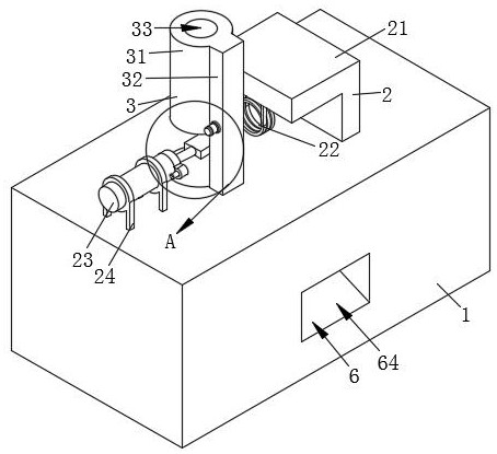
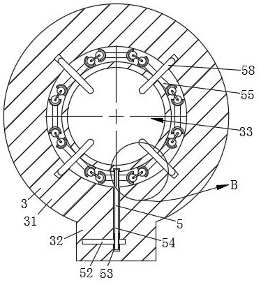
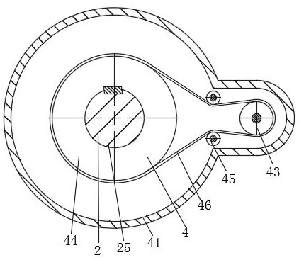
[0026] like Figure 1-Figure 8 As shown, a heat treatment device for mechanical parts of the present invention includes a main body 1, a telescopic mechanism 2, a storage mechanism 3, a turning mechanism 4, a discharging mechanism 5 and a cooling mechanism 6, which are used to place the workpiece in advance. The storage mechanism 3 is arranged on the top of the main body 1, and the telescopic mechanism 2 for operating workpieces to be heated is arranged between the storage mechanism 3 and the main body 1, and is used for operating heated workpieces to drop The turning mechanism 4 to the inside of the cooling mechanism 6 is arranged on one side of the telescopic mechanism 2, and is used to place the workpiece inside the storage mechanism 3 on the s...


PUM


Abstract

The invention relates to the field of heat treatment devices, and particularly relates to a mechanical part heat treatment device. The mechanical part heat treatment device comprises a main body, a telescopic mechanism, a material storage mechanism, a turnover mechanism, a material placing mechanism and a cooling mechanism. By arranging the material storage mechanism, workpieces can be added whilethe main body is subjected to heat treatment, so that the interruption of work is avoided, and the heat treatment efficiency is improved; by arranging the telescopic mechanism, the workpieces placedby the material placing mechanism can be heated, so that the contact of an operator is avoided, and the risk that the operator is scalded is avoided; by arranging the material placing mechanism, the workpieces can conveniently fall onto a placing part of the telescopic mechanism one by one, so that manual taking operation is replaced; by arranging the turnover mechanism, the heated workpieces canbe automatically deflected to enter the cooling mechanism, so that the automation degree of the device is improved; and by arranging the cooling mechanism, the workpieces are discharged to the outer side of the main body after being cooled, so that space is made for subsequent cooling of other workpieces.

Description

technical field [0001] The invention relates to the field of heat treatment devices, in particular to a heat treatment device for mechanical parts. Background technique [0002] Heat treatment refers to a metal thermal processing process in which materials are heated, kept warm and cooled in a solid state to obtain the desired structure and properties. During the progression from the Stone Age to the Bronze and Iron Ages, the role of heat treatment was gradually recognized. The final heat treatment of mechanical parts processing is to improve the mechanical properties of the parts such as hardness, wear resistance and strength, so as to better realize their use value; while the heat treatment of existing parts is by quenching, the purpose of quenching is to make the Cold austenite undergoes martensite or bainite transformation to obtain martensite or bainite structure, and then tempered at different temperatures to greatly improve the rigidity, hardness, wear resistance, fa...

Claims


Application Information

Patent Timeline
Patent Type & Authority Applications(China)
IPC IPC(8): C21D1/62
CPCC21D1/62
Inventor 不公告发明人
Owner 杭州心杨科技有限公司
Why Eureka
Try Eureka