
Steel plate electroplating process of Zn-Co-W alloy

An electroplating process and steel plate technology, which is applied in the electrolysis process, electrolysis components, cells, etc., can solve the problems of loose coating, uneven coating surface, and failure to consider the quality of the coating, so as to reduce the possibility of shedding and enhance the strength of van der Waals force , Improve the effect and quality of the effect

Inactive Publication Date: 2021-03-09
淮南纳创电力工程有限公司
View PDF1 Cites 2 Cited by
  • Summary
  • Abstract
  • Description
  • Claims
  • Application Information

AI Technical Summary

Problems solved by technology

[0003] There are also some technical solutions in the prior art, such as the Chinese patent with application number CN201910975528.3, which includes the following steps: S1, cleaning and degreasing the product to be electroplated; S2, acidifying the product to be electroplated after cleaning and degreasing. Washing; S3, the first electroplating; S4, spraying a liquid protective film on the surface of the product; S5, engraving patterns on the surface of the product with radium, and carving off the protective film and the electroplating layer of the first electroplating; S6, the second electroplating, the second The process of the second electroplating is different from the first electroplating; S7, the PET protective film is torn off, and the product presents two electroplating effects; in the process of electroplating the product in this scheme, the coating obtained by electroplating on the product is not considered The quality of the obtained coating may be insufficient in the bonding strength between the coating and the product, which will affect the service life of the coating. Unevenness affects the coating effect of the product after electroplating. At the same time, during use, the coating is easy to peel off at the loose place, resulting in damage to the coating and affecting the aesthetics of the product.

Method used


Image

  • Steel plate electroplating process of Zn-Co-W alloy
  • Steel plate electroplating process of Zn-Co-W alloy
  • Steel plate electroplating process of Zn-Co-W alloy

Examples


Embodiment approach

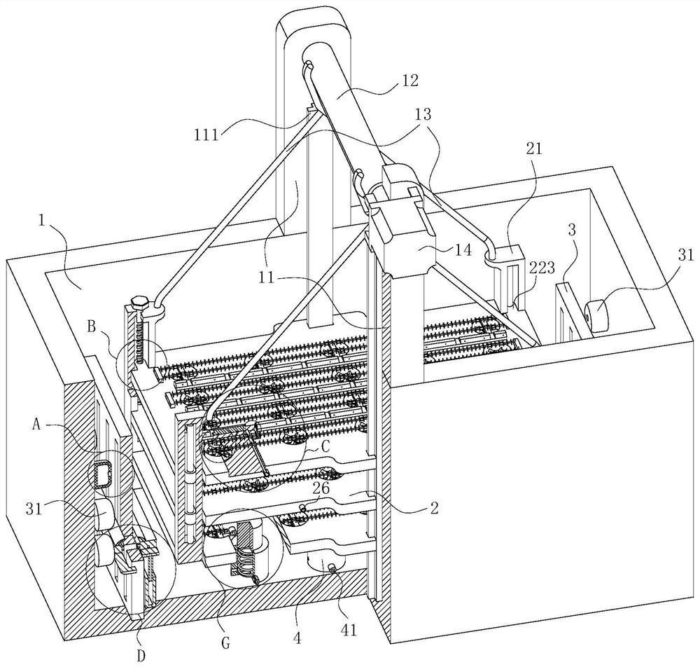
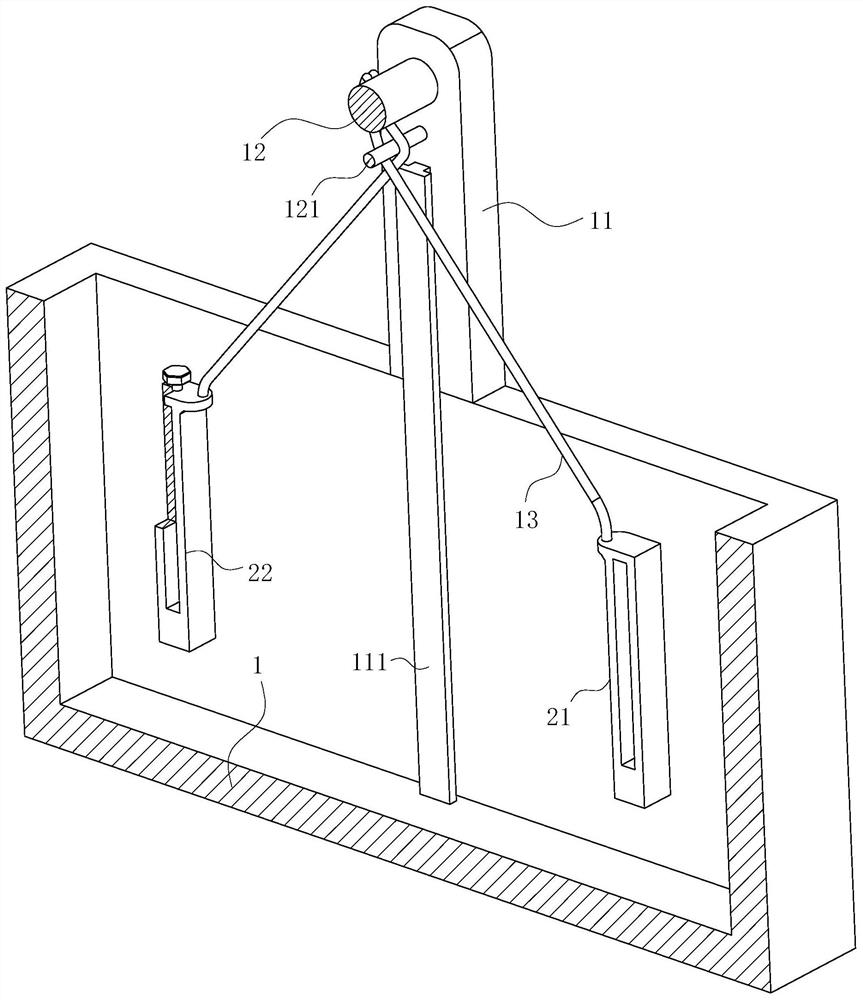
[0057] As an embodiment of the present invention, the fixed column includes a guide column 21 and an adjustment column 22; the number of the guide column 21 and the adjustment column 22 are equal; the guide column 21 is installed diagonally on the bearing plate 2; The adjustment column 22 is installed diagonally on the bearing plate 2; the lower ends of the guide column 21 and the adjustment column 22 are fixedly connected with the lowermost bearing plate 2 in the main body 1; the connection between the guide columns 21 and the adjustment The connecting lines between the columns 22 are perpendicular to each other; the optical axis is installed in the guide column 21; the second connecting block 223 is slidably installed on the optical axis; the second connecting block 223 is fixedly connected on the bearing plate 2; A screw rod 221 is installed in the adjustment column 22 for rotation; the upper end of the screw rod 221 is positioned above the adjustment column 22; the screw ro...


PUM


Abstract

The invention belongs to the technical field of surface treatment, and particularly relates to a steel plate electroplating process of a Zn-Co-W alloy. The process comprises the steps of S1, steel plate pretreatment: the surface of a Zn-Co-W alloy steel plate to be electroplated is polished, cleaned and deoiled, and then the steel plate is subjected to anodic electrolytic polishing treatment; S2,steel plate electroplating treatment: the Zn-Co-W alloy steel plate treated in the step S1 is put into an electroplating device as a cathode, and electroplating is conducted by using a direct-currentpower supply; and S3, steel plate post-treatment: after treatment in the step S2 is completed, the electroplated Zn-Co-W alloy steel plate is put into a post-treatment furnace to be subjected to heattreatment, after treatment is completed, the temperature is naturally reduced to the room temperature, and a finished product of the electroplated Zn-Co-W alloy steel plate is obtained. The steel plate electroplating process of the Zn-Co-W alloy is low in cost and easy to operate, and an obtained coating is good in performance and more attractive.

Description

technical field [0001] The invention belongs to the technical field of surface treatment, in particular to a Zn-Co-W alloy steel plate electroplating process. Background technique [0002] With the development of society, people's pursuit of product appearance is getting higher and higher, and tends to be more diversified. The appearance of products will directly affect the market competitiveness. Therefore, product appearance decoration is getting more and more attention. Zinc-cobalt-tungsten alloy has excellent performance. By electroplating the surface of the alloy steel plate, the performance of the steel plate and the appearance of the steel plate can be further improved, and the appearance of products made of zinc-cobalt-tungsten alloy can be improved to increase the attractiveness of consumers. force. [0003] There are also some technical solutions in the prior art, such as the Chinese patent with application number CN201910975528.3, which includes the following ste...

Claims


Application Information

Patent Timeline
IPC IPC(8): C25D7/00C25D17/08C25D21/10
CPCC25D7/00C25D17/08C25D21/10
Inventor 梁敏陈冠群王艳军
Owner 淮南纳创电力工程有限公司
Learn More