Melt-blowing machine and method for preparing composite cloth based on melt-blowing machine

A technology of melt-blown and sprinkler head, which is applied in the field of compound cloth and die head structure based on the melt-blown machine, which can solve the problems of low service life, frequent replacement, and failure to achieve sealing, etc.

Active Publication Date: 2021-03-09
福建智罗科技有限公司
View PDF12 Cites 0 Cited by
  • Summary
  • Abstract
  • Description
  • Claims
  • Application Information

AI Technical Summary

Problems solved by technology

Although this technical solution can adjust the size of the spinneret hole online to a certain extent, there are the following technical problems: the technical solution adopts a method of covering to adjust the size of the spinneret hole. When the diameter of the jet needs to be controlled, The cross-sectional shape of the materials ejected from different spinneret hole sizes will change, especially for the spinneret holes with circular or special-shaped cross-sectional structures, which will cause the cross-section of the ejected materials to present various irregular special-shaped structures, which will directly Affects the performance of the product and subsequent processing; the method of covering requires two smooth surfaces between the moving plate and the spinneret. If a sealing layer such as a rubber layer is set on the moving plate, although the extrusion deformation of the rubber layer can achieve a certain sealing effect, but at the same time lead to the following problems, the extrusion deformation of the sealing layer moves relative to the spinneret When contacting with the edge of the spinneret hole, it will increase mutual wear, resulting in low service life, frequent replacement, and even failure to achieve the sealing effect

Method used


Image

  • Melt-blowing machine and method for preparing composite cloth based on melt-blowing machine
  • Melt-blowing machine and method for preparing composite cloth based on melt-blowing machine
  • Melt-blowing machine and method for preparing composite cloth based on melt-blowing machine

Examples


Embodiment 1

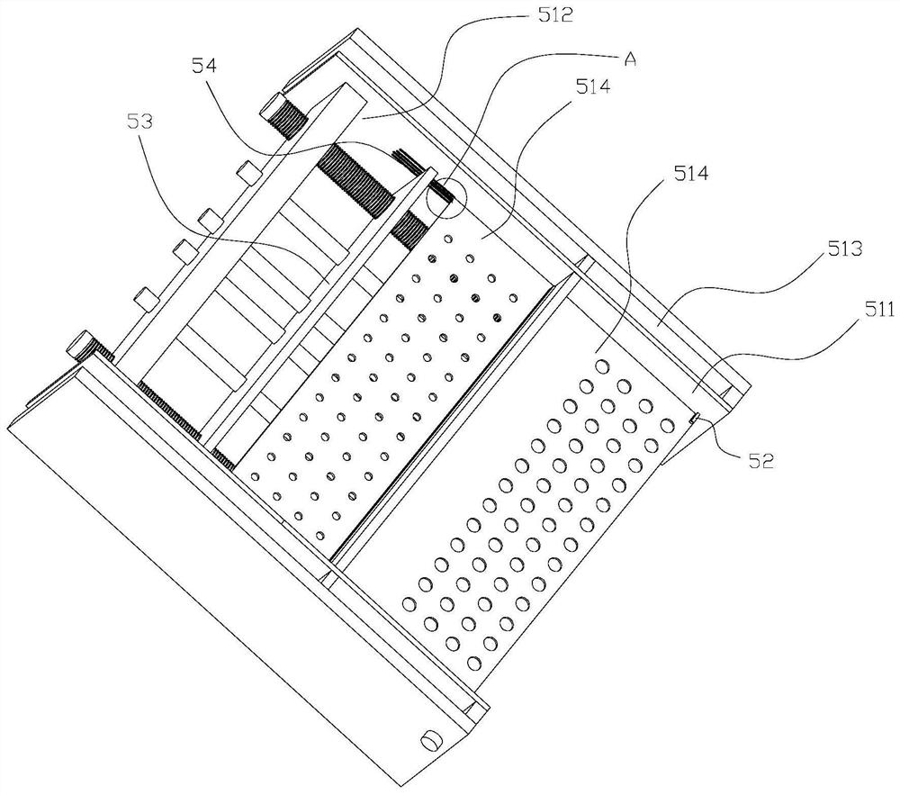
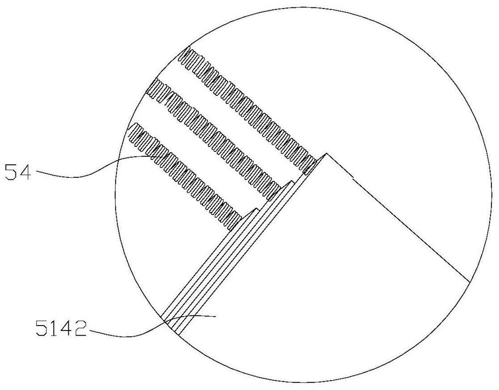
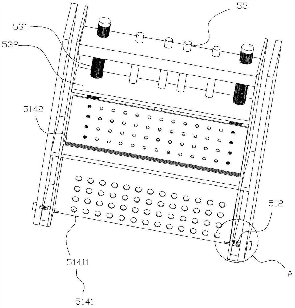
[0065] Such as Figure 1-3 As shown, this embodiment discloses a die head structure, including a die head body. The die head body includes a discharge cavity 511 , a discharge plate retractable cavity 512 , a discharge plate limit device installation cavity 513 , and a discharge plate 514 . It also includes a discharge plate limiting device 52 , a pressing device 53 and an elastic reset device 54 . The pressing device 53 is arranged in the receiving cavity 512 of the discharge plate, and the two ends of the discharge plate 514 are the protruding end 5141 and the pressing end 5142 respectively.

[0066] The pressing device 53 presses the pressing end 5142 of the discharge plate 514 to drive the protruding end 5141 of the discharge plate 514 into the discharge cavity 511 , and causes the discharge plate 514 to be in sealing contact with the discharge cavity 511 . A discharge hole 51411 is opened on the protruding end 5141 of the discharge plate 514. When a plurality of discharg...

Embodiment 2

[0097] Such as Figure 9 , 10 As shown, this implementation discloses a melt-blown nozzle head based on the die head structure of the above-mentioned embodiment. A hot air channel 5113 is opened in the discharge chamber 511, and the hot air channel 5113 surrounds the corresponding position of the outermost discharge plate 514. On the periphery of the discharge hole 51411, the hot air channel 5113 is in the form of a variable-diameter cone structure whose inner diameter decreases sequentially from the inside to the outside. It also includes a hot air pipe 581, one end of the hot air pipe 581 communicates with the hot air duct 5113, and the other end of the hot air pipe 581 communicates with an external air source.

[0098] The present invention injects hot air into the hot air pipe 581, that is, after the air is heated by the heating device of the prior art, it flows into the inner end of the hot air passage 5113 through the hot air pipe 581. Reduced variable-diameter circula...

Embodiment 3

[0102] Such as Figure 11 , 12 As shown, this embodiment discloses a melt blown machine, which also includes an extruder body 41, a metering pump, a feeding pipe 42, a nozzle, an air heater, a web forming device 43, and a winding device. The nozzle can be any of the above-mentioned implementations Example nozzles.

[0103] The extruder body 41, the metering pump, the feeding pipe 42, the air heater, and the web forming device 43 are all prior art. The extruder body 41 of the present invention can be the structure of the prior art single-screw extruder or the structure of the twin-screw extruder.

[0104] The extruder body 41 is used to melt the raw materials to obtain the melt, the metering pump is arranged on the feeding pipe 42, and the melt is input into the nozzle through the feeding pipe 42 under the action of the metering pump, and the air heater is used to heat the air. Heating, the heated air is delivered to the hot air channel 5113 through the hot air pipe 581, and...


PUM

PropertyMeasurementUnit
Melt indexaaaaaaaaaa

Abstract

The invention discloses a die head structure. A pressing device presses a pressing end of a discharging plate to drive an extending end of the discharging plate to extend into a discharging cavity; the projection of a discharging hole of the discharging plate positioned at the inner part in the axial direction completely falls into the projection of a discharging hole of the discharging plate positioned at the outer part in the axial direction; a discharging plate opening groove is formed in the side face of the extending end of the discharging plate, and the depth of the discharging plate opening groove positioned at the inner part is smaller than that of the discharging plate opening groove positioned at the outer part; one end of each pressing block can be pressed on the corresponding discharging plate opening groove; and discharging plate limiting devices are moved in the direction opposite to the discharging plates so that the discharging plates can sequentially move towards discharging plate containing cavities until the discharging holes are limited in the discharging plate containing cavities again under reset of corresponding elastic reset devices from inside to outside. The invention further discloses a melt-blowing machine and a method for preparing composite cloth. The die head structure has the advantage that the discharging holes can be conveniently and quickly changed on line.

Description

technical field [0001] The invention relates to the technical field of melt-blown cloth, in particular to a die head structure and a method for preparing composite cloth based on the melt-blown machine. Background technique [0002] The melt-blown cloth uses high-speed hot air flow to draw the polymer melt stream extruded from the spinneret hole (discharge hole) of the die head, thereby forming ultra-fine fibers and collecting them on the condensing screen or roller, and at the same time Self-adhesive to become a melt-blown nonwoven fabric. [0003] The preparation method of the melt-blown cloth of the prior art is disclosed in a patent application 200810119520.9, a kind of ultra-fine melt-blown non-woven fabric hybrid material, the melt-blown non-woven fabric prepared by it and its manufacturing method, by combining polypropylene I and polypropylene II After mixing according to the mass ratio of 10:90 to 90:10, granulation is carried out. After the granules obtained by gra...

Claims


Application Information

Patent Timeline
IPC IPC(8): D01D5/098D01D4/02D04H1/544D04H1/558D04H3/007D04H3/14B32B27/02B32B27/32B32B27/12B32B37/06B32B37/10B65H18/02B65H18/10
CPCD01D5/0985D01D4/02D01D4/025D04H1/544D04H1/558D04H3/14D04H3/007B32B5/022B32B5/26B32B37/06B32B37/10B65H18/10B65H18/028B32B2262/0253
Inventor 陈文忠肖文峰
Owner 福建智罗科技有限公司
Why Eureka
Try Eureka