an air conditioning unit

A technology for air-conditioning units and compressors, applied in refrigerators, compressors, refrigeration components, etc., can solve the problems of small pressure difference in the cooling system for supplying refrigerants, different working stages of power modules, and different heat dissipation, etc., to improve the temperature uniformity. , expand the working temperature area, and achieve the effect of differential adjustment

Active Publication Date: 2022-08-09
CSR ZHUZHOU ELECTRIC LOCOMOTIVE RES INST
View PDF6 Cites 0 Cited by
  • Summary
  • Abstract
  • Description
  • Claims
  • Application Information

AI Technical Summary

Problems solved by technology

In the actual operation process, in different stages of unit operation, the power module works in different stages, and the heat dissipation will also be different; for example, in the process of unit startup, the power is relatively large, but the pressure difference of the supply refrigerant cooling system is small, Causes a certain over-temperature risk to the start-up process, but currently there is no corresponding control and adjustment measures

Method used


Image

  • an air conditioning unit
  • an air conditioning unit
  • an air conditioning unit

Examples


Embodiment 1

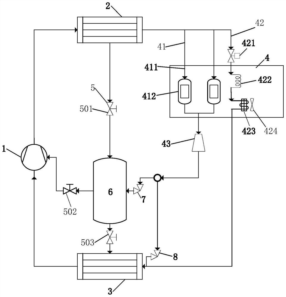
[0029] like figure 1 As shown, the air conditioning unit of this embodiment includes a refrigeration system and a frequency converter. The refrigeration system includes a compressor 1, a condenser 2, a main evaporator 3, a flasher 6 and a throttling unit 5. The inlet end of the compressor 1 is connected to the The main evaporator 3 is connected, the outlet end is connected to the condenser 2, the throttle unit 5 includes a first throttle element 501, a second throttle element 502 and a third throttle element 503, the first throttle element 501 is located in the condenser 2 Between the flasher 6, the second throttle element 502 is located between the compressor 1 and the flasher 6, the third throttle element 503 is located between the flasher 6 and the main evaporator 3, and the inverter is provided with The inverter cooling unit 4, the inlet end of the inverter cooling unit 4 is connected to the condenser 2, the outlet end of the inverter cooling unit 4 is connected to the fla...

Embodiment 2

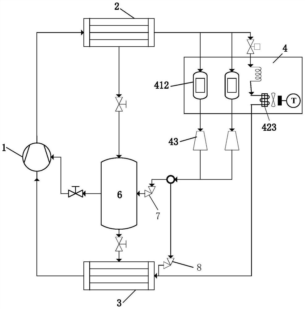
[0040] like image 3 As shown, the difference between this embodiment and the first embodiment is that the installation positions of the first switch module 43 and the second switch module 44 are different. In this embodiment, each cooling branch 411 is provided with the first switch module 43 or and / and the second switch module 44 , specifically, each cooling branch 411 is provided with a cooler 412 and a first switch module 43 , and each first switch module 43 is located on the cooling branch 411 corresponding to the outlet end of the cooler 412 . A first switch module 43 is configured on each cooling branch 411 , which can independently adjust each cooling branch 411 , improve the temperature uniformity of the cooler 412 , and realize differential adjustment, which is suitable for the loss of each cooling branch 411 There are certain differences (for example, the heat dissipation of the power devices is different); on this basis, the first switch module 43 is located downst...


PUM


Abstract

The invention discloses an air conditioning unit, comprising a refrigeration system and a frequency converter. The refrigeration system includes a compressor, a condenser, a main evaporator, a flasher and a throttling unit. The inlet end of the compressor is connected with the main evaporator, and the outlet end is connected to the main evaporator. connected with the condenser, the throttle unit includes a first throttle element, a second throttle element and a third throttle element, the first throttle element is located between the condenser and the flasher, The second throttling element is located between the compressor and the flasher, and the third throttling element is located between the flasher and the main evaporator, characterized in that the frequency converter is provided with The inverter cooling unit, the inlet end of the inverter cooling unit is connected to the condenser, the outlet end of the inverter cooling unit is connected to the flasher through the first switch, and is connected to the flasher through the second switch. The main evaporators are connected. The air-conditioning unit of the invention has the advantages of simple structure, anti-condensation, and suitability for different working conditions.

Description

technical field [0001] The invention mainly relates to the technical field of power electronic thermal management, in particular to an air conditioning unit. Background technique [0002] The frequency conversion of refrigeration and heat pump units has stronger working condition adjustment ability, which is an effective measure to improve the unit's ability to adjust. The frequency conversion of central air conditioners has become an industry trend. The inverter of the unit adopts refrigerant cooling, which has the advantages of high efficiency, simplicity, cleanliness, strong economy and convenient maintenance. However, the thermal management of the inverter is also more complex, requiring a better thermal management system. [0003] The thermal management load inside the inverter of refrigeration and heat pump units is usually divided into two parts, one part is the heat of the power device, and the other part is the heat of other components. The heat of the power devi...

Claims


Application Information

Patent Timeline
Patent Type & Authority Patents(China)
IPC IPC(8): F25B1/00F25B41/31F25B41/37F25B49/02H05K7/20
CPCF25B1/00F25B49/02H05K7/20945F25B2600/05Y02B30/70
Inventor 何凯马明王春燕姚磊冯钊赞李奎吴辉田恩李诗怀
Owner CSR ZHUZHOU ELECTRIC LOCOMOTIVE RES INST
Why Eureka
Try Eureka