
Stepper for juxtaposedly pushing three or four piezoelectrics and scanning probe microscope body thereof

A technology of piezoelectric scanning tube and piezoelectric body, which is applied in the direction of piezoelectric devices/electrostrictive devices, instruments, and parts of instruments, etc., which can solve the problem of small nano-precision stepper size, large working temperature range, and driving force. Large and other problems, to achieve the effect of large driving force, large working temperature zone and small size

Inactive Publication Date: 2010-12-08
UNIV OF SCI & TECH OF CHINA
View PDF10 Cites 0 Cited by
  • Summary
  • Abstract
  • Description
  • Claims
  • Application Information

AI Technical Summary

Problems solved by technology

[0006] In order to solve the problem that the existing nano-precision steppers cannot have small size, simple and firm structure, large driving force and large working temperature range at the same time, a stepper with three or four piezoelectric bodies propelled in parallel and a stepper made of it are provided. Scanning probe microscope body capable of working in small spaces

Method used


Image

  • Stepper for juxtaposedly pushing three or four piezoelectrics and scanning probe microscope body thereof
  • Stepper for juxtaposedly pushing three or four piezoelectrics and scanning probe microscope body thereof
  • Stepper for juxtaposedly pushing three or four piezoelectrics and scanning probe microscope body thereof

Examples


Embodiment 1

[0058] Embodiment 1: Stepper with parallel propulsion of basic three piezoelectric bodies

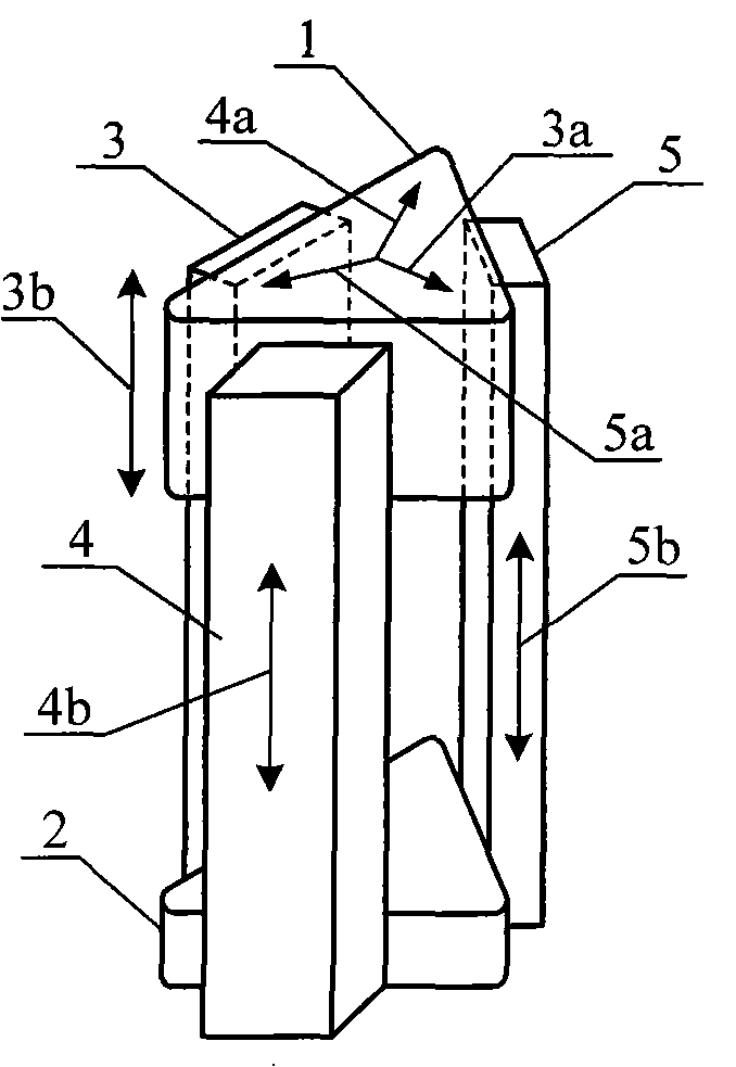
[0059] see figure 1 , a basic stepper with three piezoelectric bodies in parallel, including a slider 1, a base 2 and three piezoelectric bodies: piezoelectric body 1 3, piezoelectric body 2 4 and piezoelectric body 3 5, characterized by The three piezoelectric bodies 3, 4 and 5 are fixedly standing on the base 2 in a triangular arrangement parallel to the expansion and contraction directions 3b, 4b and 5b, and are arranged in the same direction as the three piezoelectric bodies 3, 4 and 5 in the expansion and contraction direction. The upper part is the sliding block 1, and the positive pressure 3a that presses the free ends of the three piezoelectric bodies 3, 4, and 5 against the sliding block 1 is set in the direction perpendicular to the expansion and contraction of the three piezoelectric bodies 3, 4, and 5. , 4a and 5a, among the maximum static friction forces generated by the t...

Embodiment 2

[0063]Embodiment 2: A stepper for parallel propulsion of elastic tri-piezoelectric bodies

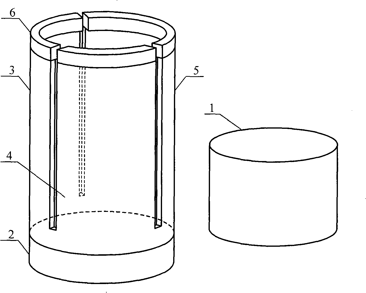
[0064] In Embodiment 1, the positive pressures 3a, 4a and 5a that press the slider 1 and the free ends of the three piezoelectric bodies 3, 4 and 5 can be passed through the elasticity of the slider 1 itself (for example, attached Figure 4 The tubular slider cut in the center) and / or the elasticity of the three piezoelectric bodies 3, 4 and 5 themselves and / or the addition of elastic bodies (for example, in the attached Figure 4 Place the spring in the cut tubular slider) to achieve.

Embodiment 3

[0065] Embodiment 3: A stepper for parallel propulsion of integral type three piezoelectric bodies

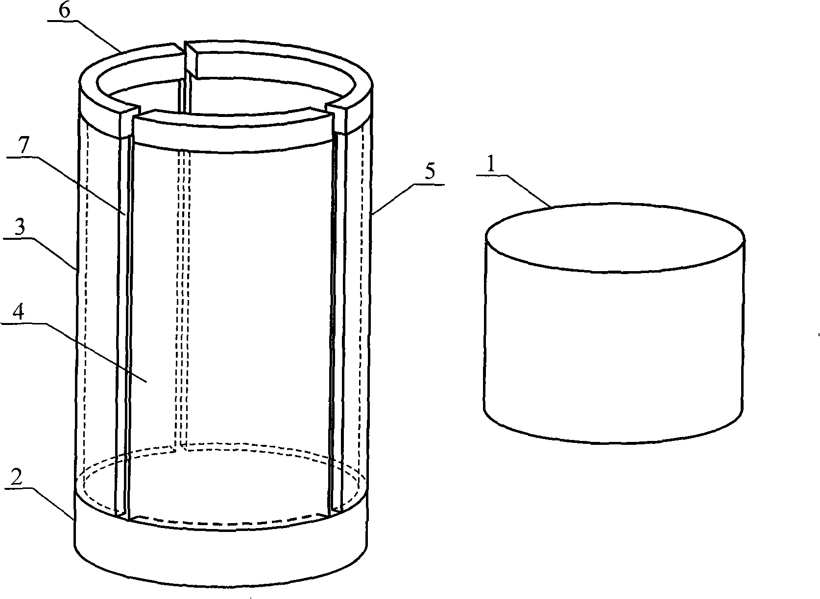
[0066] The three piezoelectric bodies 3, 4 and 5 in the above embodiment can be different parts of a complete piezoelectric body, and the three piezoelectric bodies 3, 4 and 5 can also form a complete piezoelectric body with the base 2. Different parts of the electric body can be realized by dividing the electrodes and cutting the piezoelectric body, as long as the expansion and contraction of the three piezoelectric bodies 3, 4 and 5 are independently controllable. For example, the outer electrode of a complete cylindrical piezoelectric tube is divided into three third cylindrical electrodes along the axial direction, and then the piezoelectric tube is cut along the gap between the three electrodes but not completely cut, so that the piezoelectric tube The three cut parts of the electric tube constitute the three piezoelectric bodies 3, 4 and 5, and the uncut part can be regar...


PUM


Abstract

The invention relates to a stepper for juxtaposedly pushing three or four piezoelectrics and a scanning probe microscope body thereof, in particular to a piezoelectric locator comprising three or fourThe invention relates to a stepper for juxtaposedly pushing three or four piezoelectrics and a scanning probe microscope body thereof, in particular to a piezoelectric locator comprising three or foure piezoelectrics and the base can be arranged integrally, and a piezoelectric scanatron fixed on the base is coated outside the stepper, thus a scanning probe microscope body which can work in a smalhe piezoelectrics and the base can be arranged integrally, and a piezoelectric scanatron fixed on the base is coated outside the stepper, thus a scanning probe microscope body which can work in a small space is formed. The invention has small size, simple and firm structure, and large working temperature zone and driving force, is suitable for various extreme physical conditions and approaches tol space is formed. The invention has small size, simple and firm structure, and large working temperature zone and driving force, is suitable for various extreme physical conditions and approaches toan ideal stepper.an ideal stepper. piezoelectrics, a base and slide blocks, wherein the three or four piezoelectrics which are triangularly or squarely arranged and are parallel in the telescopic direction are juxtaposedly fixed and epiezoelectrics, a base and slide blocks, wherein the three or four piezoelectrics which are triangularly or squarely arranged and are parallel in the telescopic direction are juxtaposedly fixed and elevated on the base; the slide blocks which are in sliding match with the three or four piezoelectrics in the telescopic direction are provided; positive pressures which enable the slide blocks and thlevated on the base; the slide blocks which are in sliding match with the three or four piezoelectrics in the telescopic direction are provided; positive pressures which enable the slide blocks and the free ends of the piezoelectrics to be pressed are arranged in the direction vertical to the telescopic direction; in the largest breakout friction to the slide blocks, which is generated by the three free ends of the piezoelectrics to be pressed are arranged in the direction vertical to the telescopic direction; in the largest breakout friction to the slide blocks, which is generated by the three or four positive pressures, any largest breakout friction is smaller than the sum of other two or three frictions; the slide blocks press the free ends of the piezoelectrics through elastic force; te or four positive pressures, any largest breakout friction is smaller than the sum of other two or three frictions; the slide blocks press the free ends of the piezoelectrics through elastic force; th

Description

technical field [0001] The invention relates to a piezoelectric stepper, in particular to a stepper propelled by three or four piezoelectric bodies in parallel and a mirror body of a scanning probe microscope made of the stepper, which belongs to the technical field of piezoelectric positioners. Background technique [0002] At the same time, it has nano-level positioning accuracy, millimeter-level large stroke, large working temperature range from ultra-low temperature to higher than room temperature, large driving force, small size, simple and firm structure and simple and reliable control. It is a coveted positioning tool for atomic / molecular manipulation and even subatomic structure imaging, especially in the field of nanoscience research under extreme physical conditions such as ultra-low temperature and ultra-strong magnetic field, it is even more inseparable from such an ideal positioning device. For example, ultra-low temperature conditions can generally only be obta...

Claims


Application Information

Patent Timeline
Patent Type & Authority Patents(China)
IPC IPC(8): H01L25/16H01L41/09G12B21/20
Inventor 施益智陆轻铀
Owner UNIV OF SCI & TECH OF CHINA
Learn More