
Grinding tool detection equipment for optical cable processing

A testing equipment and grinding technology, applied in the direction of measuring device, testing of mechanical parts, testing of machine/structural parts, etc., can solve the problems of prolonging the processing cycle of optical fiber and cable, low working efficiency of cutting device, and reducing the practicability of cutting device. , to achieve better fixed effect, enhanced practicability and applicability, and reduced uncertainties

Inactive Publication Date: 2021-03-09
陈利
View PDF4 Cites 0 Cited by
  • Summary
  • Abstract
  • Description
  • Claims
  • Application Information

AI Technical Summary

Problems solved by technology

[0003] During the processing of optical fiber and cable, a cutting device is needed to cut the optical fiber and cable. When cutting the optical fiber and cable, workers mostly cut it manually, which leads to the low efficiency of the existing cutting device, prolongs the processing cycle of the optical fiber and cable, and reduces the practicability of the cutting device. , and the cutting equipment needs to be maintained regularly, which increases its labor intensity, and the cutting equipment cannot be tested while the optical cable is being processed, which greatly reduces its applicability

Method used


Image

  • Grinding tool detection equipment for optical cable processing
  • Grinding tool detection equipment for optical cable processing
  • Grinding tool detection equipment for optical cable processing

Examples


Embodiment Construction

[0029] The following will clearly and completely describe the technical solutions in the embodiments of the present invention with reference to the accompanying drawings in the embodiments of the present invention. Obviously, the described embodiments are only some, not all, embodiments of the present invention. Based on the embodiments of the present invention, all other embodiments obtained by persons of ordinary skill in the art without making creative efforts belong to the protection scope of the present invention.

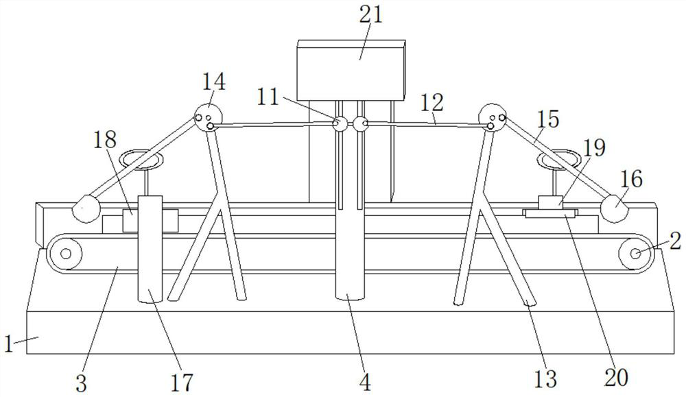
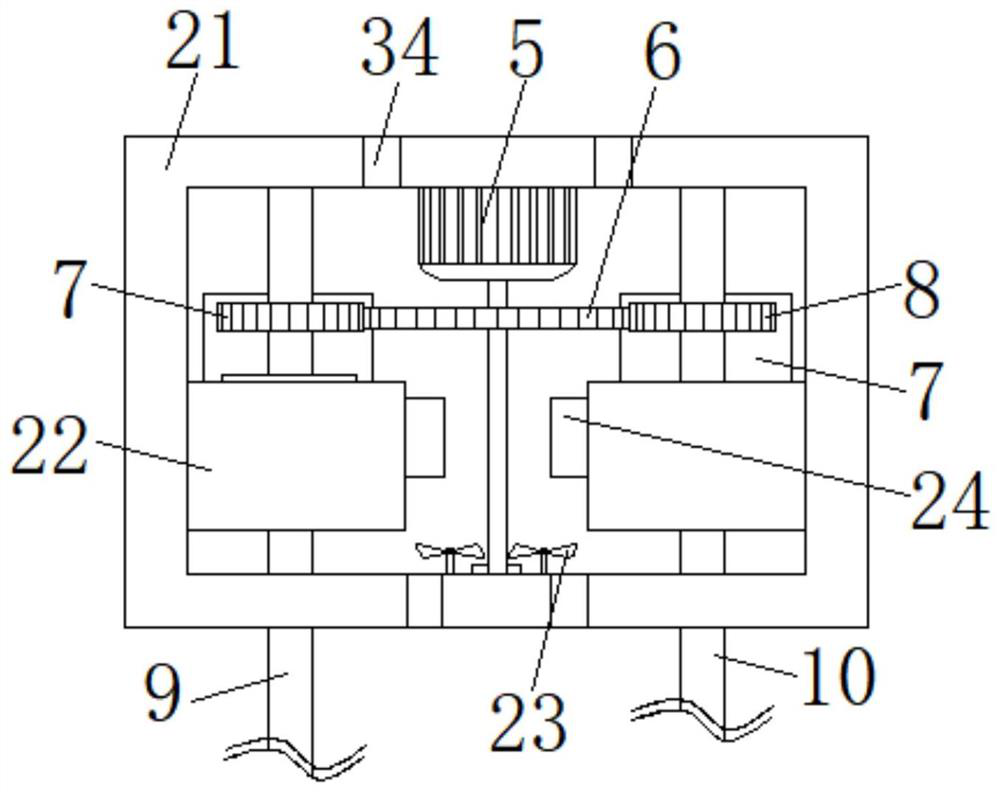
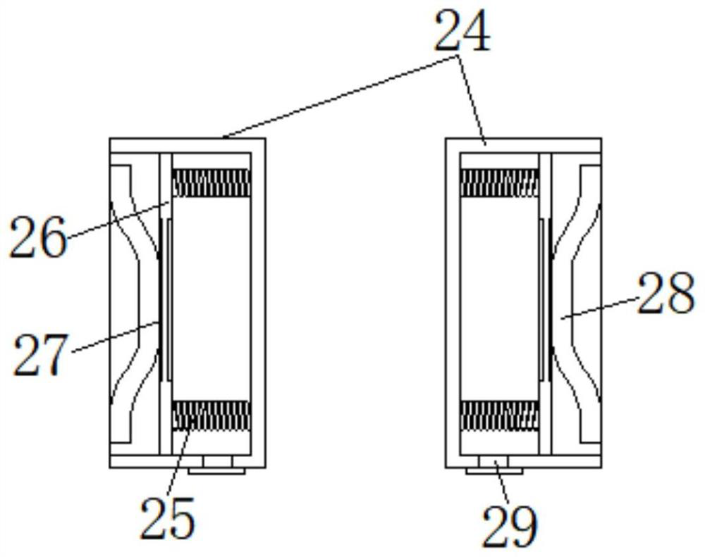
[0030] see Figure 1-6 , the present invention provides a technical solution: a grinding tool detection device for optical cable processing, comprising a processing table 1, a driving roller 2 and a transmission belt 3, the top of the processing table 1 is fixedly equipped with a driving roller 2, and the number of driving rollers 2 is Two, and a transmission belt 3 is connected between the two driving rollers 2. The top of the transmission belt 3 is provided ...


PUM


Abstract

The invention discloses grinding tool detection equipment for optical cable machining. The equipment comprises a machining table, two driving rollers and a transmission belt, wherein the driving rollers are fixedly mounted at the top of the machining table, the transmission belt is in transmission connection between the two driving rollers, and a hob is arranged at the top of the transmission belt; a frame body is fixedly installed on the front face of the machining table, a driving motor is inlaid in the top of the frame body, an oil adding mechanism is installed on the machining table, and the driving motor is inlaid in the inner top wall of the oil adding mechanism. According to the grinding tool detection equipment for optical cable processing, gas in the sealing box is pressed into the gas guide pipe and filled into the oil storage space due to shaking of the push plate, so that the air pressure in the oil storage space is increased, and the grinding tool detection equipment has the advantages that lubricating oil easily blocks the oil inlet due to the fact that the oil inlet is small, and lubricating oil cannot block the oil inlet by increasing the air pressure in the oil storage space; therefore, the shockproof effect of the oil adding mechanism is achieved.

Description

technical field [0001] The invention relates to the technical field of optical cable processing, in particular to a grinding tool detection device for optical cable processing. Background technique [0002] A fiber optic cable is a communication cable consisting of two or more glass or plastic optical fiber cores within a protective cladding and covered by a plastic PVC outer sleeve, the signal transmission along the inner optical fiber typically using infrared light , Optical fiber communication is one of the important ways of modern information transmission. It has the advantages of large capacity, long relay distance, good confidentiality, no electromagnetic interference and copper saving. [0003] During the processing of optical fiber and cable, a cutting device is needed to cut the optical fiber and cable. When cutting the optical fiber and cable, workers mostly cut it manually, which leads to the low efficiency of the existing cutting device, prolongs the processing c...

Claims


Application Information

Patent Timeline
IPC IPC(8): G01M13/00
CPCG01M13/00
Inventor 陈利
Owner 陈利
Learn More