Truss welded steel bar welding mechanism

A welding mechanism and steel bar technology, applied in the direction of welding equipment, auxiliary welding equipment, welding/cutting auxiliary equipment, etc., can solve the problems of low welding efficiency, reduced production efficiency, and low effective utilization rate of welding mechanisms, so as to avoid welding errors, Improved production efficiency and reduced electrode loss

Pending Publication Date: 2021-03-12
CHENGDU GUTE MACHIENRY WORKS
View PDF0 Cites 4 Cited by
  • Summary
  • Abstract
  • Description
  • Claims
  • Application Information

AI Technical Summary

Problems solved by technology

[0003] In the prior art, the welding efficiency of the welding mechanism of the truss is low. The truss is welded and formed in the order from front to back. During the welding process, the welding torch is fixed. During the welding process, the electrodes are placed on other parts of the The mechanism is easy to disperse the current, the electrode loss is large, the effective utilization rate is low, and the production efficiency is low; in addition, the truss is transmitted and welded through the transmission mechanism, so that when the unwelded part is welded, the front end has been welded. Deformation occurs, resulting in unqualified finished products and reducing production efficiency

Method used


Image

  • Truss welded steel bar welding mechanism
  • Truss welded steel bar welding mechanism
  • Truss welded steel bar welding mechanism

Examples


Embodiment Construction

[0035] The present invention will be further described in detail below in conjunction with the accompanying drawings, so that those skilled in the art can implement it with reference to the description.

[0036] It should be understood that terms such as "having", "comprising" and "including" as used herein do not entail the presence or addition of one or more other elements or combinations thereof.

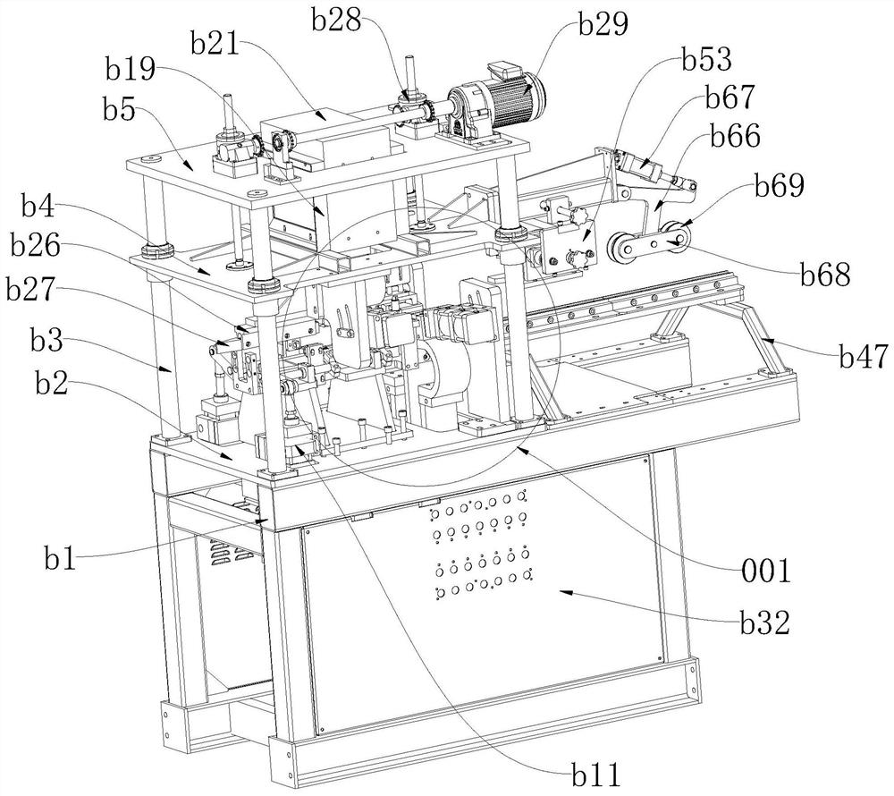
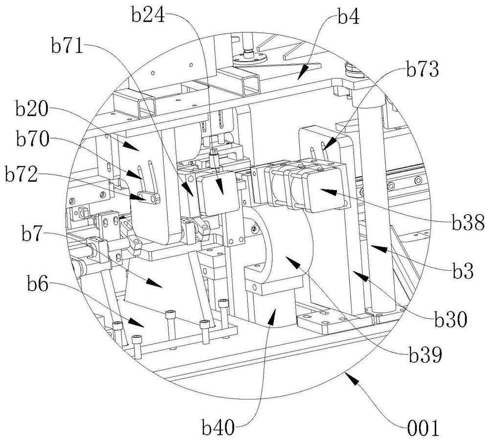
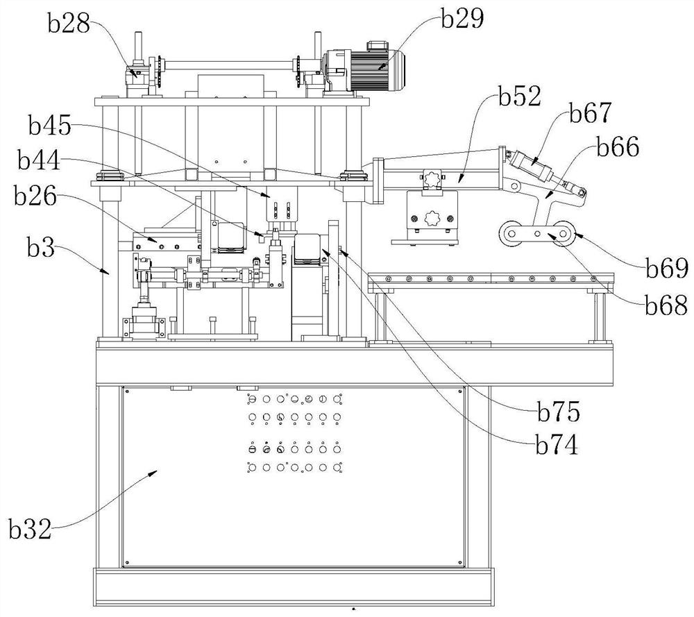
[0037] Figure 1-10 It shows a truss welding steel bar welding mechanism of the present invention, including: a bracket b1, the truss steel bar entry end of the support b1 is the front section, and the truss steel bar output end is the rear section; a fixed platform is fixed on the front section of the support b1 b2, the upper surface of the front end of the fixed platform b2 is installed with an upper welded support assembly for supporting the truss, and the two sides of the upper welded support assembly are symmetrically provided with a web reinforcement positioning assembly; t...


PUM


Abstract

The invention discloses a truss welded steel bar welding mechanism. The truss welded steel bar welding mechanism comprises a support, a truss steel bar feeding end of the support is a front section, and a truss steel bar output end of the support is a rear section; a fixing platform is fixed to the front section of the support, an upper welding supporting assembly used for supporting a truss is installed on the upper surface of the front end of the fixing platform, and web member rib positioning assemblies are symmetrically arranged on two sides of the upper welding supporting assembly; an upper welding mechanism is installed above the adjustable upper welding supporting assembly, and the upper welding mechanism moves vertically through a height adjusting mechanism; a lower welding mechanism used for welding truss lower chord ribs is installed at the rear end of the fixing platform, and an upper chord rib pressing assembly is installed at the front end of the upper portion of the lowerwelding mechanism; and an anti-magnetization guide assembly is installed on the rear section of the support, and an anti-lateral-bending assembly is arranged above the anti-magnetization guide assembly. The truss welded steel bar welding mechanism is high in welding efficiency, capable of saving energy and environmentally friendly.

Description

technical field [0001] The invention relates to the field of truss production, in particular to a truss welding steel bar welding mechanism. Background technique [0002] A truss is a group of components that form a triangle or a combination of several triangles in a specific way. Usually, these trusses are welded by steel bars. Reinforced trusses use steel bars as structural materials, which are welded, cut into long sections, and handed over for use. The cross-section of the steel truss is triangular, and the whole includes an upper chord bar located at the top corner and two lower chord bars located at the two bottom corners, while the two waists are two abdominal bars bent in a wave shape. The wave-shaped peaks and troughs of the abdominal bars are respectively The upper chord and the lower chord are welded together to form a whole steel truss; sometimes, due to engineering needs, it is necessary to fold up the protruding feet of the lower chord and the trough of the ab...

Claims


Application Information

Patent Timeline
Patent Type & Authority Applications(China)
IPC IPC(8): B23K37/02B23K37/04B23K37/00
CPCB23K37/02B23K37/0443B23K37/00
Inventor 邹鹏汪东林简华涛赵刚
Owner CHENGDU GUTE MACHIENRY WORKS
Why Eureka
Try Eureka