
Machining center water curtain system

A machining center and water curtain technology, applied in metal processing equipment, metal processing machinery parts, manufacturing tools, etc., can solve the problems of debris residue, high cost, troublesome nozzle installation, etc., to achieve cost saving, simple installation, and improved effect Effect

Pending Publication Date: 2021-03-12
南京纳威精密机械有限公司
View PDF5 Cites 0 Cited by
  • Summary
  • Abstract
  • Description
  • Claims
  • Application Information

AI Technical Summary

Problems solved by technology

However, there will be certain defects when using nozzles for spraying. Directly use nozzles to spray debris. Because the water curtain sprayed by the nozzles is not uniform and the contact with the bottom plate is not sufficient, this will cause some debris to remain. On the bottom plate, and the installation of the nozzle is troublesome and the cost is high

Method used


Image

  • Machining center water curtain system
  • Machining center water curtain system
  • Machining center water curtain system

Examples


Embodiment

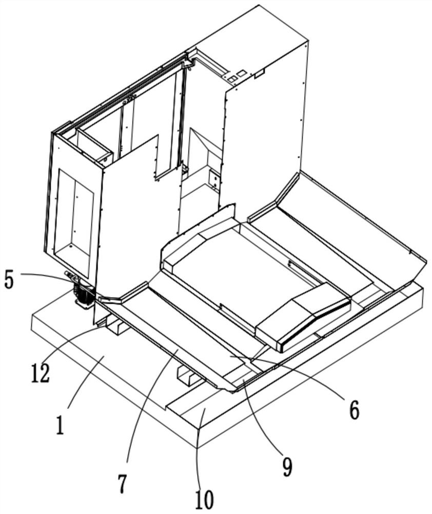
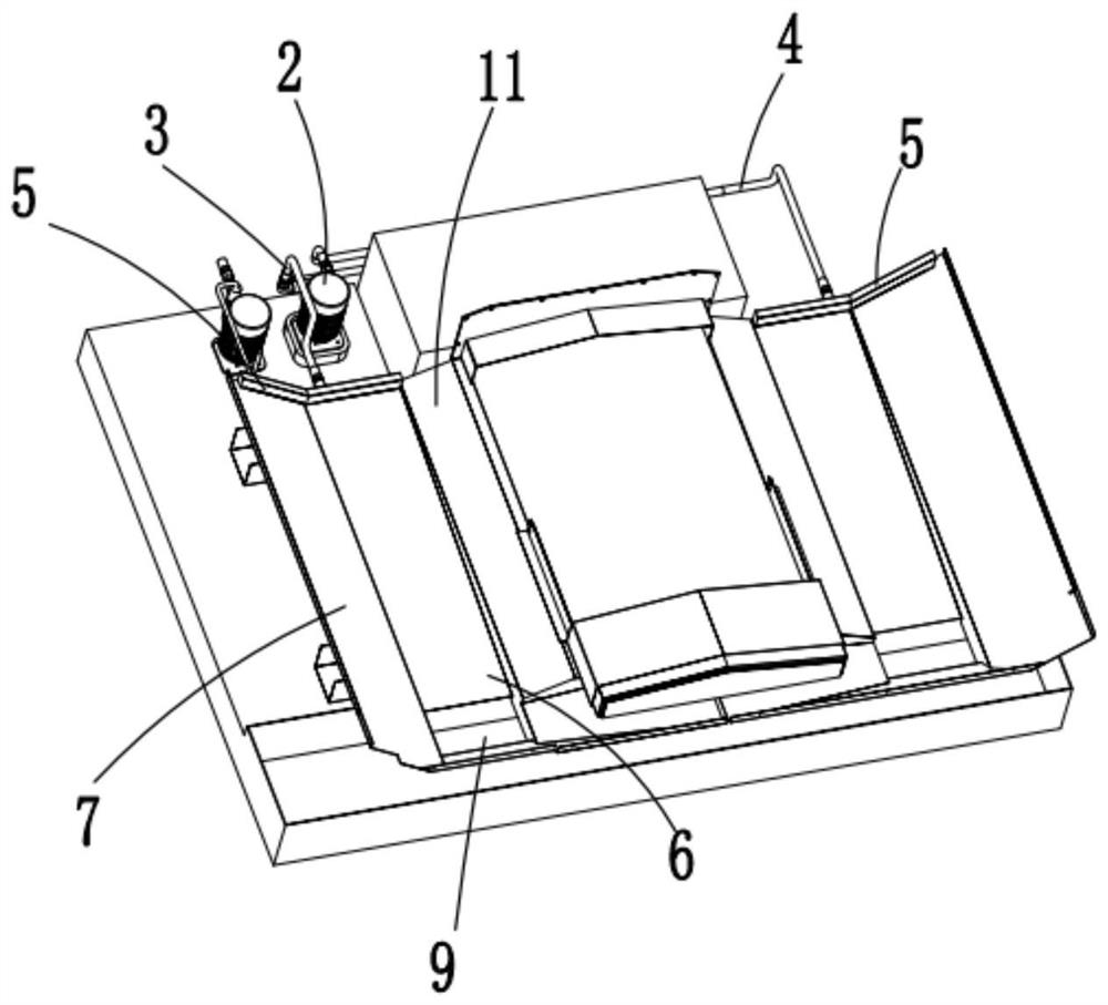
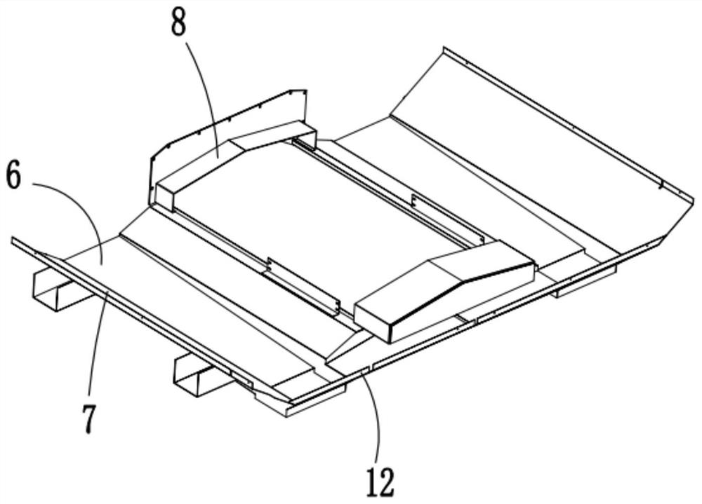
[0024] Such as figure 1 As shown, the water curtain system of the machining center of the present invention includes a water tank 1, a water pump 2 and a shower pipe 5. The water pump 2 is arranged on the top of the water tank 1 and draws water in the water tank 1 into the shower pipe 5. The water pump 2 The water outlets are respectively connected to the first water pipe 3 and the second water pipe 4. The first water pipe 3 and the second water pipe 4 respectively extend to the left and right sides of the top of the foundation and are connected to the shower pipe 5. The water pump 2 draws the shower liquid in the water tank 1 through The first water pipe 3 and the second water pipe 4 are respectively transported into the two shower pipes 5, and are flushed out through the shower pipes 5, and the flushed shower liquid forms a water curtain on the bottom plate to take away the debris attached to the bottom plate. crumbs.

[0025] Such as figure 2 As shown, the base plate is ...


PUM


Abstract

The invention discloses a machining center water curtain system, and relates to the field of machining center waste chip recovery. The machining center water curtain system comprises a water tank, a water pump and shower pipes, wherein the water pump is arranged at the top of the water tank and pumps water in the water tank into the shower pipe, a water outlet of the water pump is connected with afirst water pipe and a second water pipe, the first water pipe and the second water pipe extend to the left side and the right side of the top of a foundation respectively and are connected with theshower pipes, a bottom plate is laid at the top of the foundation, the shower pipes are symmetrically arranged along the left side and the right side of the bottom plate, water outlets of a strip-shaped structure are formed in the side walls of the shower pipes, cooling water sprayed from the water outlets is sprayed from one end of the bottom plate to the other end of the bottom plate to form a water curtain, chip removal openings are formed in the ends, opposite to the shower pipes, of the bottom plate, a recycling box is arranged under the chip removal openings, the shower pipes can form awater curtain with the larger area and higher flushing force, the bottom plate is evenly flushed, chips left on the bottom plate can be rapidly flushed into the recycling box to be recycled, and the flushing effect is effectively improved.

Description

technical field [0001] The invention relates to the field of waste recycling of machining centers, in particular to a water curtain system of a machining center. Background technique [0002] Machining center is a high-efficiency automatic machine tool suitable for processing complex parts composed of mechanical equipment and numerical control system. CNC machining centers are currently one of the most productive and widely used CNC machine tools in the world. Its comprehensive processing ability is strong, and the workpiece can complete more processing content after one clamping, and the processing accuracy is high. [0003] During the machining process of the machining center, cutting workers will produce chips, which will fall onto the base plate. Existing machining centers usually use nozzles to shower the chips on the base plate. However, there will be certain defects when using nozzles for spraying. Directly use nozzles to spray debris. Because the water curtain spra...

Claims


Application Information

Patent Timeline
IPC IPC(8): B23Q11/00B23Q11/10
CPCB23Q11/0042B23Q11/0067B23Q11/10Y02P70/10
Inventor 崔耀中
Owner 南京纳威精密机械有限公司
Learn More