Rotary grinding equipment for iron plate weld mark of hardware

A welding mark and rotary technology, which is applied in metal processing equipment, grinding/polishing equipment, and machine tools suitable for grinding the edge of workpieces, etc., can solve the problems of waste damage to work efficiency and low efficiency, and achieve good grinding effect, Increases safety and prevents damage

Inactive Publication Date: 2021-03-12
廖子宁
View PDF9 Cites 8 Cited by
  • Summary
  • Abstract
  • Description
  • Claims
  • Application Information

AI Technical Summary

Problems solved by technology

[0004] In order to overcome the disadvantages that the waste generated by manual grinding of welding marks will cause harm to people and the work efficiency is not high, the technical problem is to provide a rotary grinding equipment for welding marks of iron plates for hardware that can automatically collect waste and has high work efficiency

Method used


Image

  • Rotary grinding equipment for iron plate weld mark of hardware
  • Rotary grinding equipment for iron plate weld mark of hardware
  • Rotary grinding equipment for iron plate weld mark of hardware

Examples


Embodiment 1

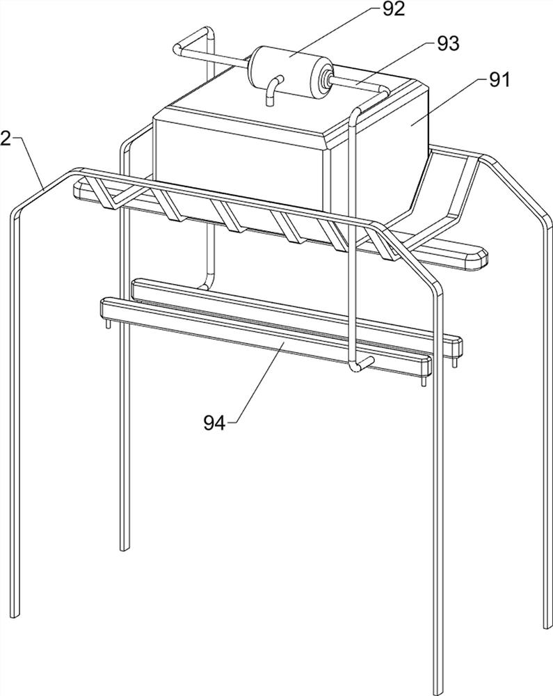
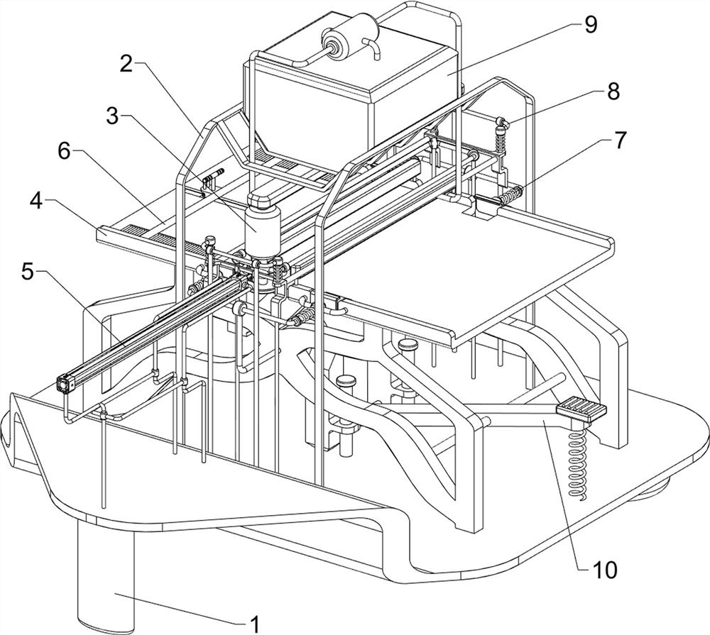
[0074] A kind of rotary grinding equipment for welding marks of iron plates for hardware, such as figure 1 As shown, it includes a base 1, a first support frame 2, a motor 3, a placement assembly 4 and a grinding assembly 5, a first support frame 2 is provided in the middle of the top of the base 1, and a motor 3 is slidingly provided on the top of the first support frame 2. A placement component 4 is provided on the top right side of the base 1, and a grinding component 5 is provided between the top left side of the base 1 and the output shaft of the motor 3.

[0075] When people need to polish the welding mark on the iron plate, first put the welded iron plate on the placement assembly 4, then start the motor 3, and the output shaft of the motor 3 drives a certain part of the grinding assembly 5 to rotate, so that the grinding assembly 5. Grind the welding marks. After the grinding is completed, turn off the motor 3 and remove the polished iron plate.

Embodiment 2

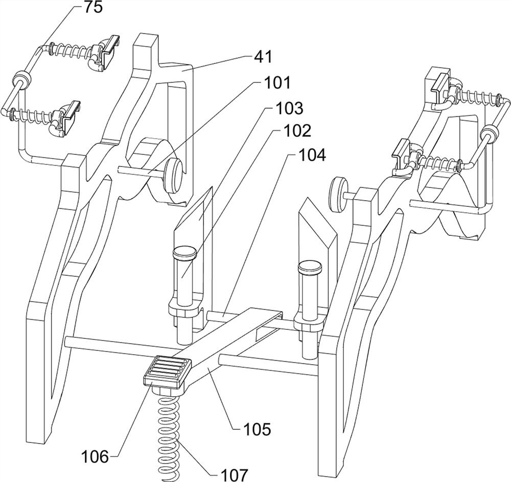
[0077] On the basis of Example 1, such as figure 2 , image 3 , Figure 4 , Figure 5 and Figure 6 As shown, the placement assembly 4 includes a support plate 41, a placement plate 42 and a first baffle plate 43, a support plate 41 is arranged symmetrically on the right side of the top of the base 1, and a placement plate 42 is provided between the tops of the support plates 41, and the placement plate 42 First baffles 43 are provided on both left and right sides.

[0078] When people need to polish the welding marks on the iron plate, the welded iron plate can be placed on the front side of the top of the placement plate 42, and then the iron plate can be pushed back to a suitable position. Under the action, prevent the iron plate from falling.

[0079] The grinding assembly 5 includes a first support rod 51, a first connecting rod 52, a diamond 53, a second support frame 54, a cylinder 55 and a push rod 56, the middle of the top of the base 1 is provided with a first ...

Embodiment 3

[0086] On the basis of Example 2, such as Figure 7 , Figure 8 , Figure 9 and Figure 10 As shown, a locking assembly 8 is also included, and the locking assembly 8 includes a third support rod 81, a third guide rod 82, a block 83, a third connecting rod 84, a third spring 85, a second wedge block 86, a fourth Connecting rod 87 and torsion spring 88, base 1 top left and right sides middle parts are all provided with the 3rd support rod 81, the inner side of the 3rd support rod 81 upper part is equipped with the 3rd guide rod 82 symmetrically before and after, the 3rd guide rod 82 of the same side All sliding type is provided with clamping block 83 between the bottom, and clamping block 83 cooperates with the second connecting rod 75, is provided with the third connecting rod 84 symmetrically front and back between the upper part of the inner side of clamping block 83, and both sides of clamping block 83 top front and back are all with the same. A third spring 85 is provid...


PUM


Abstract

The invention relates to grinding equipment, in particular to rotary grinding equipment for iron plate welding mark of hardware. The rotary grinding equipment for the iron plate welding mark of the hardware has the advantages of automatic collection of scraps and high working efficiency. The rotary grinding equipment for the iron plate welding mark of the hardware comprises a base, a first supportframe arranged in the top middle of the base, a motor arranged at the upper part of the first support frame slidably, a placing assembly arranged on one side of the top of the base, and a grinding assembly arranged between one side of the top of the base and an output shaft of the motor. Through cooperation of the placing assembly and the grinding assembly, the weld mark on an iron plate can be automatically ground, and the working efficiency of people is improved; injuries caused by manual operation can be avoided, and the safety of people is improved; the grinding effect is good, and through a locating assembly, the welding mark can be aligned to the position under diamond; and the grinding precision is improved.

Description

technical field [0001] The invention relates to a grinding device, in particular to a rotary grinding device for welding marks on an iron plate for hardware. Background technique [0002] Welding, also known as welding, is a manufacturing process and technology for joining metals or other thermoplastic materials by means of heating, high temperature or high pressure. There are many energy sources for modern welding, including gas flames, electric arcs and lasers. After the material is welded, welding marks will be left, which will affect the aesthetics. Therefore, after welding the metal materials, the welding marks will be polished off. [0003] In terms of the current technology, the welding marks are usually polished manually. The accuracy of the manual operation is not high, and the metal material needs to be manually fixed, which is time-consuming and laborious, which affects people's work efficiency. In addition, the waste generated during grinding Chips will be scatt...

Claims


Application Information

Patent Timeline
Patent Type & Authority Applications(China)
IPC IPC(8): B24B9/04B24B41/02B24B55/06B24B41/06B24B47/06B24B47/12
CPCB24B9/04B24B41/02B24B55/06B24B41/06B24B47/06B24B47/12
Inventor 廖子宁
Owner 廖子宁
Why Eureka
Try Eureka