

Discharge lamp operating apparatus and method
A technology for controlling equipment and control methods, which is applied to the use of gas discharge lamps, the layout of electric lamp circuits, and electric light sources, etc., and can solve the problems of reduced excitation arc straightening mode frequency superposition effect and discharge arc curvature reduction, etc.
- Summary
- Abstract
- Description
- Claims
- Application Information
AI Technical Summary
Problems solved by technology
Method used
Image

Examples
Embodiment 1
[0067] Figure 7A is a block diagram of the discharge lamp control apparatus 2 of the first embodiment of the present invention for a metal halide lamp 1 of 35 watts. It is to be noted that the 35 W metal halide lamp 1 in this embodiment is a mercury-filled discharge lamp in which sodium iodide and scandium iodide metal halides are sealed in a glass envelope defining a discharge space.
[0068] The control device 2 applies a current having a specific waveform to the 35W metal halide lamp 1 to start and drive the lamp.
[0069] The control device 2 includes a 150 kHz sine wave generator 3 , a 400 Hz rectangular wave generator 4 and a wave synthesizer 5 .
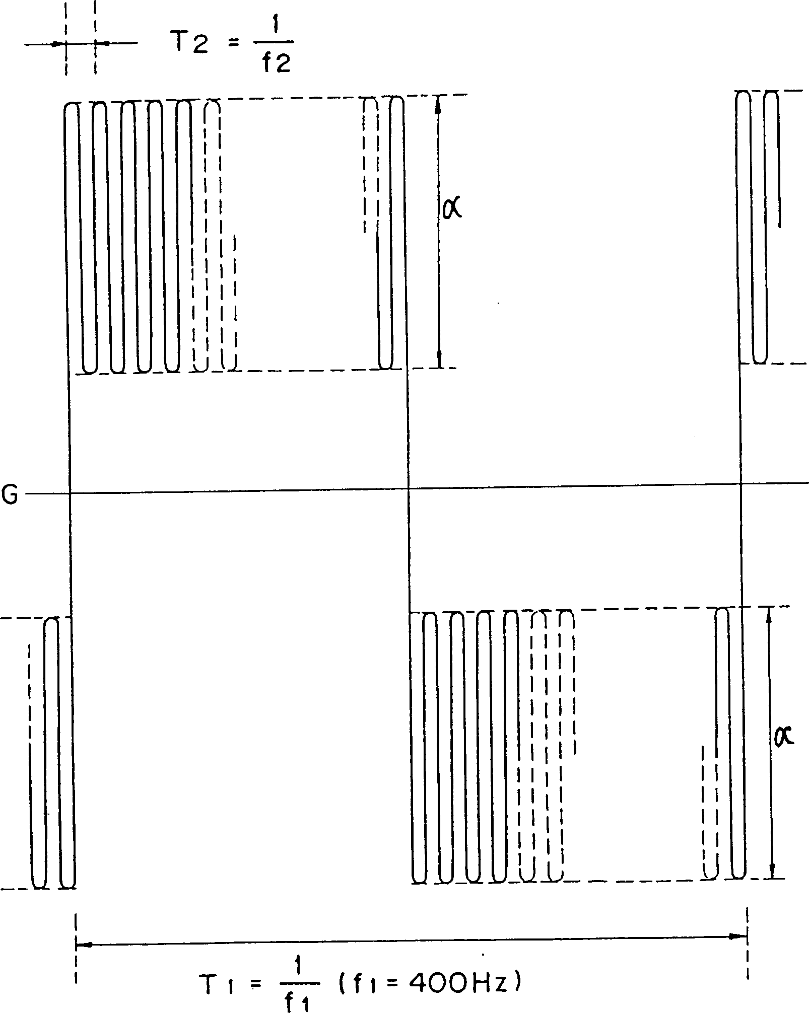
[0070] The sine wave generator 3 is an AC power source A which outputs a waveform of an acoustic resonant frequency component for exciting a linear mode arc. The rectangular wave generator 4 is a polarity-changing power source for outputting a waveform with a frequency lower than the acoustic resonance frequency and for cha...
Embodiment 2
[0078] Figure 9 is a block diagram of a discharge lamp control apparatus 12 according to a second embodiment of the present invention for a 35-watt metal halide lamp 1, the 35-watt metal halide lamp 1 and Figure 7A The lamp 1 shown is the same.
[0079] The discharge lamp control device 12 in this case includes a DC power source 13 , a rectangular wave conversion circuit 14 and an igniter 15 .
[0080] The DC power source 13 outputs a DC waveform superimposed on a waveform having an acoustic resonance frequency component for exciting a linear mode arc. The rectangular wave conversion circuit 14 is a conversion circuit for changing the polarity of the output of the DC power source 13 according to the low-sound resonance frequency. The igniter 15 is an igniter for supplying a high voltage sufficient to start the discharge of the 35 W metal halide lamp 1 .
[0081] The DC power source 13 includes a DC power source 16 , a high frequency power source 17 and a superposition cir...
Embodiment 3
[0093] Figure 11 is used with Figure 7A A block diagram of a discharge lamp control device 40 according to a third embodiment of the invention for a 35-watt metal halide lamp with the same lamp 1 as shown.
[0094] It should be noted that the discharge lamp control device 40 of this embodiment is used to start and control a 35W metal halide lamp 1, and it includes a DC power source 41, a rectangular wave conversion circuit 14 and an igniter 15.
[0095] The DC power source 41 outputs a DC waveform superimposed on a waveform having a frequency component of an acoustic resonance frequency that excites a discharge arc in a linear mode. The rectangular wave conversion circuit 14 is a conversion circuit that changes the output polarity of the DC power source 41 at a frequency lower than the acoustic resonance frequency. The igniter 15 is an igniter that supplies a high voltage sufficient to start the discharge of the 35 W metal halide lamp 1 .
[0096] It should be noted that ...
PUM
 Abstract
Description
Claims
Application Information