Method for guiding oil well dosing by utilizing oil well indicator diagram data
A dynamometer and oil well technology, which is used in wellbore/well components, earthwork drilling, construction, etc., can solve the problems of dosing time and dosing amount manually set, unable to meet the digital development of oilfields, and difficult to guarantee the effect. , to achieve unattended, improve dosing efficiency and digital management level of oil wells, and reduce the number of times of production
- Summary
- Abstract
- Description
- Claims
- Application Information
AI Technical Summary
Problems solved by technology
Method used
Image
Examples
Embodiment 1
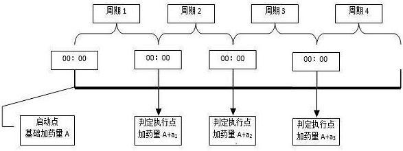
[0035] This embodiment provides a method of using oil well dynamometer data to guide oil well dosing, using an intelligent oil well dosing system to periodically add dosing to the oil well, wherein the dosing amount in the first cycle is the basic dosing amount A. The amount of dosing in each subsequent cycle is determined according to the load increase of the oil well surface dynamometer diagram in the previous cycle.
[0036] The invention adopts an intelligent oil well dosing system to automatically set the dosing amount of the wax-removing and anti-waxing agent, realizes the closed-loop control of the intelligent dosing of the oil well, improves the dosing efficiency and the digital management level of the oil well, and realizes unattended dosing at the wellhead.
Embodiment 2
[0038] On the basis of Embodiment 1, this embodiment provides a method of using oil well dynamometer data to guide oil well dosing. The intelligent oil well dosing system includes intelligent RTU, wellhead dosing device, angular displacement sensor and load sensor , the wellhead dosing device includes a PLC controller and a dosing pump, the dosing pump is electrically connected to the PLC controller, the angular displacement sensor is arranged on the beam of the pumping unit, and the load sensor is arranged at the wellhead on the sucker rod;
[0039] The intelligent RTU is electrically connected to the PLC controller, the angular displacement sensor and the load sensor are connected to the intelligent RTU with electrical signals, and the angular displacement sensor and the load sensor are used to transmit data to the intelligent RTU to obtain the oil well ground indicator picture.
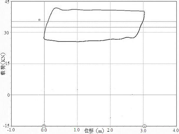
[0040] The surface dynamometer diagram is more than 200 synchronous load and displacement data...
Embodiment 3
[0042]On the basis of Embodiment 1 or 2, this embodiment provides a method for using oil well dynamometer data to guide oil well dosing, which specifically includes the following steps:
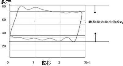
[0043] Step 1) Determine the difference between the maximum and minimum values of the oil well surface dynamometer load after hot washing or pump inspection, and use the minimum value of the difference between the maximum and minimum values as the standard value Z 0 ;Such as figure 1 shown;
[0044] Step 2) Start the intelligent oil well dosing system. At the beginning of the first dosing cycle, the smart RTU sends the dosing volume command to the wellhead dosing device for dosing, and enters the first dosing cycle;
[0045] Step 3) After the first dosing cycle ends, the smart RTU calculates the average value of the difference between the maximum and minimum values of the ground dynamometer load in the first dosing cycle Z 1 , and with the standard value Z 0 Make a comparison to g...
PUM
 Abstract
Description
Claims
Application Information
 - R&D
- Intellectual Property
- Life Sciences
- Materials
- Tech Scout
- Unparalleled Data Quality
- Higher Quality Content
- 60% Fewer Hallucinations
Browse by: Latest US Patents, China's latest patents, Technical Efficacy Thesaurus, Application Domain, Technology Topic, Popular Technical Reports.
© 2025 PatSnap. All rights reserved.Legal|Privacy policy|Modern Slavery Act Transparency Statement|Sitemap|About US| Contact US: help@patsnap.com


