
Underground coal mine working face lower end plugging slurry blocking wall and process

A technology of working face and slurry wall, which is applied in mining equipment, filling materials, earth cube drilling and mining, etc., which can solve the threat to the life safety of on-site operators, poor water filtration effect of filling and sealing wall, and long construction time of sealing wall, etc. problems, to achieve the effect of preventing wall collapse, preventing roof sinking, and reducing labor intensity

Inactive Publication Date: 2021-03-12
XINWEN MINING GROUP
View PDF0 Cites 0 Cited by
  • Summary
  • Abstract
  • Description
  • Claims
  • Application Information

AI Technical Summary

Problems solved by technology

The sealing wall formed by this process has the following problems in the on-site filling process: 1. Some mine filling operations sometimes have the problem of slurry running and collapsing during the filling process, which threatens the life safety of on-site operators; 2. The construction time of the sealing wall on site Many, low efficiency; 3. The labor intensity of the on-site workers is high; 4. The water filtration effect of the filling and sealing wall is poor, and the strength of the filling body formed is low, and the support effect on the roof is poor

Method used


Image

  • Underground coal mine working face lower end plugging slurry blocking wall and process
  • Underground coal mine working face lower end plugging slurry blocking wall and process
  • Underground coal mine working face lower end plugging slurry blocking wall and process

Examples


Embodiment 1

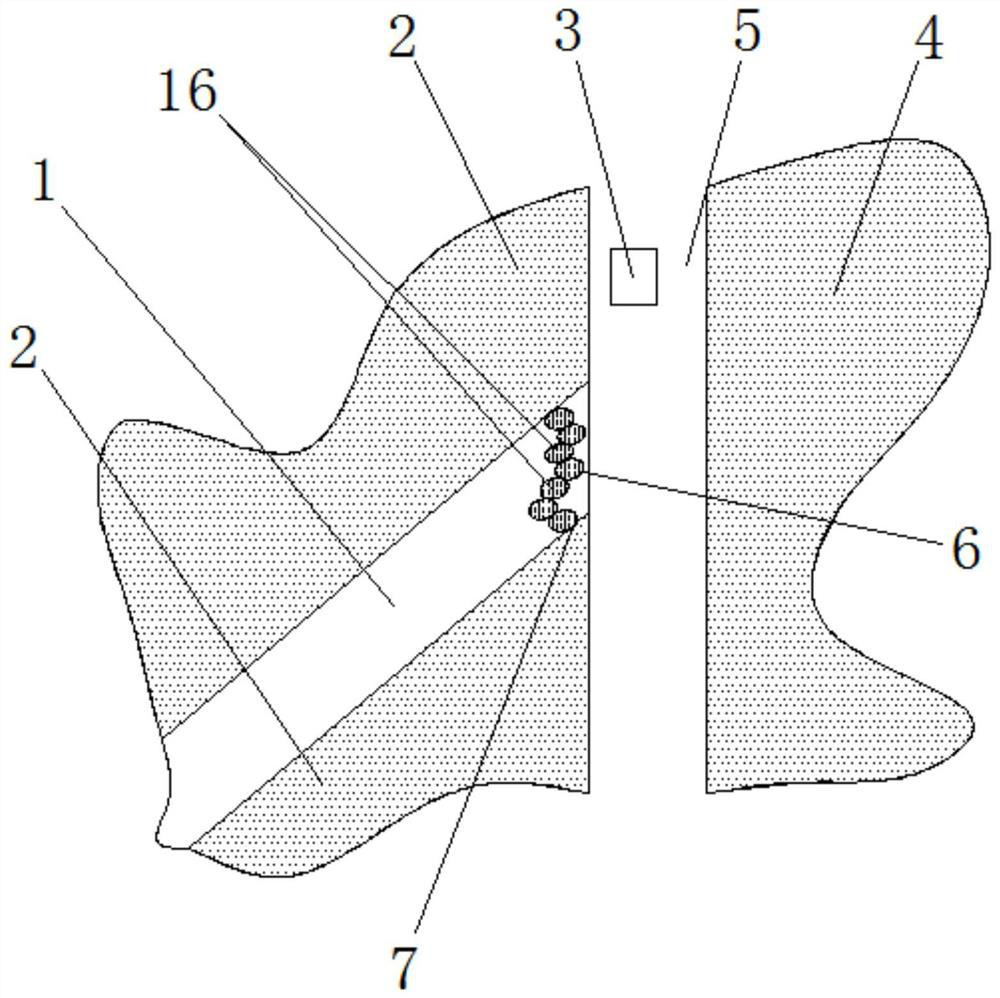
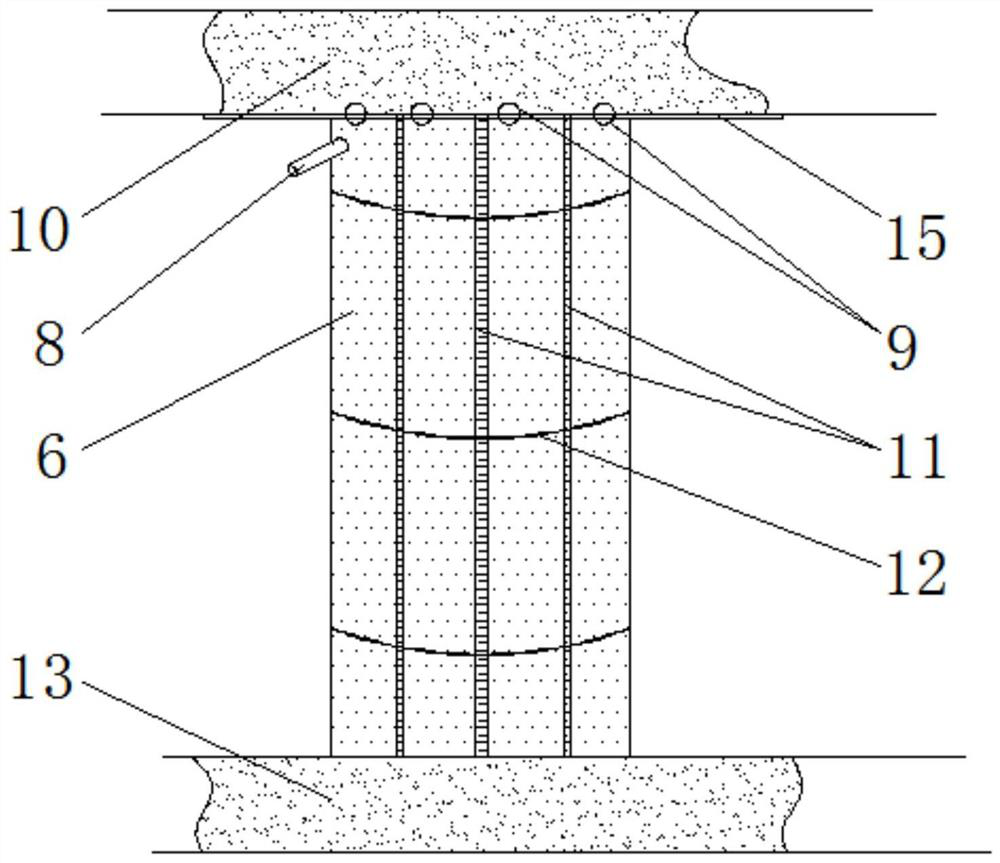
[0039] An underground coal mine working face lower end sealing slurry wall, such as figure 1 As shown, it is located at the end side of the filling branch roadway 1 connected to the transportation roadway 5 (that is, the lower end of the filling branch roadway 1). The filling branch roadway 1 is located in the middle of the first coal area 2, and the transportation roadway 5 is located between the first coal area 2 and the second coal area. Between the coal area 4, the top of the lower end of the filling branch roadway 1 is provided with a roof 10, and the bottom of the lower end of the filling branch roadway 1 is provided with a bottom plate 13; The flexible membrane piers 16 arranged side by side, such as figure 2As shown, the flexible film pier 16 includes a flexible film bag 6 vertically installed between the top plate 10 and the bottom plate 13 (the flexible film bag 6 is made of a material with strong tensile strength, good elongation performance, cold resistance and he...

Embodiment 2

[0053] In this embodiment, the difference between the lower end of the working face of the underground coal mine and the embodiment 1 is that:

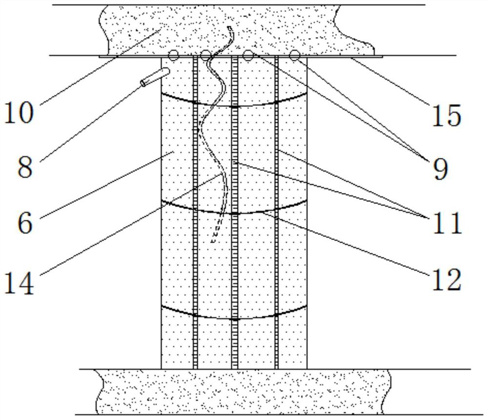
[0054] In this example, if image 3 As shown, each anchor 15 corresponding to the flexible film bag 6 is fixed with a chain 14 that hangs down into the flexible film bag 6 . After the chain 14 is installed, grouting is carried out again. After the filler is injected into the flexible membrane bag 6 and solidified and formed, a reinforced concrete structure is directly formed, which can improve the strength, stability and reliability of the flexible membrane pier 16.

[0055] In this embodiment, the filling materials include cement, sulphoaluminate, silicate and potassium salt, and their parts by mass are: 65 parts of cement, 17 parts of sulphoaluminate, 18 parts of silicate, potassium salt 8 servings.

[0056] Others are with embodiment 1.

[0057] The difference between the process of sealing the slurry wall at the lower end of th...

Embodiment 3

[0063] In this embodiment, the difference between the lower end of the working face of the underground coal mine and the embodiment 2 is that:

[0064] In this example, if Figure 4 As shown, the top plate 10 is fixed with a projection 17 extending downward to the inner side of the flexible film bag 6 , and the bottom of the projection 17 is lower than the grouting port 8 . After grouting, after the filling in the flexible film bag 6 is solidified and formed, the bumps 17 are buried in the filling, which can improve the connection stability between the filling and the top plate 10 .

[0065] In this embodiment, the filling materials include cement, sulphoaluminate, silicate and potassium salt, and their parts by mass are: 70 parts of cement, 20 parts of sulphoaluminate, 15 parts of silicate, potassium salt 5 servings.

[0066] Others are with embodiment 2.

[0067] The difference between the process of sealing the slurry wall at the lower end of the above-mentioned undergro...


PUM

PropertyMeasurementUnit
strengthaaaaaaaaaa

Abstract

The invention discloses an underground coal mine working face lower end plugging slurry blocking wall and process, and belongs to the technical field of coal mine filling mining. The plugging slurry blocking wall comprises flexible film pier columns which are closely arranged one by one in the width direction of a filling branch roadway; each flexible film pier column comprises a flexible film bagvertically arranged between a roof and a floor and a filling material injected into the flexible film bag to be solidified and formed; and the upper end of one side of the flexible film bag is connected with a grouting opening communicating with the inner side of the flexible film bag. The process comprises the following steps of firstly hanging the flexible film bag, and then injecting the filling material into the flexible film bag to form the plugging slurry blocking wall. The safe and efficient plugging of the lower end of the filling branch roadway can be effectively achieved; in addition, the field operation of the plugging process is simple; the safety performance is high; the labor intensity of field workers can be obviously reduced; the occurrence of accidents such as wall collapse and slurry leakage is effectively avoided; the safe production of the mine is guaranteed; the field construction time of the plugging wall is short, and the efficiency is high; and the formed filling body has high strength, and the supporting effect on the roof is good.

Description

technical field [0001] The invention relates to the technical field of mine filling and mining, in particular to an underground coal mine working face lower end sealing grout retaining wall and a process thereof. Background technique [0002] With the continuous improvement of the level of mining mechanization, the Permian coal seams of the upper coal formation in the central and eastern regions of my country have been fully mined, and the remaining resources are mainly "three-down-upper" pressed coal. As a green mining technology, gangue cemented filling mining technology has the characteristics of "high filling rate and low bleeding rate" compared with other filling mining technologies. Provide a technical idea for the problem of "pressed coal mining". The safe and efficient plugging of the lower end of the filling face is a key part of the gangue cemented filling mining technology, and the rationality of the plugging process is related to the success or failure of the te...

Claims


Application Information

Patent Timeline
Patent Type & Authority Applications(China)
IPC IPC(8): E21F15/00E21F15/04C04B28/00
CPCC04B28/00E21F15/00E21F15/04C04B22/14C04B22/00C04B22/08
Inventor 张志勇耿华锋王东生李全水宋美丽单绍磊
Owner XINWEN MINING GROUP
Learn More