Magnetofluid sealing device capable of realizing multistage gas diversion

A magnetic fluid sealing and gas shunting technology, which is applied to the sealing of engines, pipe components, mechanical equipment, etc., can solve the problems of large limitations in gas path design and complex processing methods, and achieve convenient air pipe layout design and multi-stage design. The effect of gas splitting and strong bearing capacity

Active Publication Date: 2021-03-12
杭州慧翔电液技术开发有限公司
View PDF9 Cites 0 Cited by
  • Summary
  • Abstract
  • Description
  • Claims
  • Application Information

AI Technical Summary

Problems solved by technology

[0005] In order to overcome the technical problems in the prior art that gas generally enters the cavity directly through a stationary shell, the design of the overall gas path is limited, and the processing method is relatively complicated, the present invention provides a magnetic valve that can realize multi-stage gas shunting. Fluid sealing device, the gas enters the rotating shaft through the dynamic seal and between the dynamic seals, and then enters the cavity through the deep hole on the rotating shaft, the air pipe arrangement design is more convenient, and the design and processing of the shell is simpler

Method used


Image

  • Magnetofluid sealing device capable of realizing multistage gas diversion
  • Magnetofluid sealing device capable of realizing multistage gas diversion

Examples


Embodiment

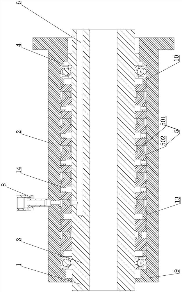
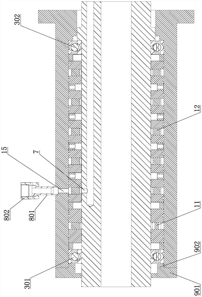
[0027] Such as figure 1 and figure 2As shown, a magnetic fluid sealing device capable of realizing multi-stage gas splitting includes a transmission shaft 1, a base 2 sleeved outside the transmission shaft, and bearings 3 and magnetic fluid are respectively arranged between the two ends of the base and the transmission shaft. The sealing assembly 5 is provided with a diversion hole 6 on the transmission shaft, and one end of the diversion hole communicates with the cavity, and an air hole 7 communicating with the diversion hole is provided on the peripheral surface of the transmission shaft. The first bearing 301 and the second bearing 302 on the side, the air hole is located between the first bearing and the second bearing, and the air supply assembly 8 is provided on the base; the magnetic fluid sealing assembly includes magnetic fluid, permanent magnet 501 and the permanent magnet The magnetic pole 502 on both sides, the magnetic fluid is arranged between the magnetic pol...


PUM


Abstract

In order to solve the technical problems that in the prior art, gas generally and directly enters a cavity through a static shell, overall gas path design limitation is large, and the machining mode is complex, the invention provides a magnetofluid sealing device capable of achieving multistage gas diversion, and the magnetofluid sealing device comprises a transmission shaft and a base arranged outside the transmission shaft in a sleeving mode, wherein bearings and magnetic fluid sealing assemblies are respectively arranged between two ends of the base and the transmission shaft, a flow guidehole is formed in the transmission shaft, one end of the flow guide hole communicates with the cavity, and air holes communicating with the flow guide hole are formed in the circumferential face of the transmission shaft; and the bearings comprise a first bearing and a second bearing which are respectively located on two sides of each magnetic fluid sealing assembly; the air holes are located between the first bearing and the second bearing, and an air supply assembly is arranged on the base. Gas enters a rotating shaft through a dynamic seal part and the space between dynamic seals and then enters the cavity through deep holes in the rotating shaft, the arrangement design of gas pipes is more convenient, and the design and machining of the shell are simpler.

Description

technical field [0001] The invention relates to the technical field of magnetic fluid sealing, in particular to a magnetic fluid sealing device capable of realizing multi-stage gas splitting. Background technique [0002] Magnetic fluid sealing technology is a new type of sealing method. It refers to the use of magnetic fluid with high saturation magnetic strength to seal related mechanical equipment. Since magnetic fluid itself is a liquid fluid, it has the basic characteristics of liquid fluid and has The magnetism of magnetic solid materials, the magnetic fluid sealing technology is based on the use of the magnetic fluid's response to the magnetic field. The magnetic fluid seal is mainly composed of two parts, namely the magnetic fluid and the specially designed magnetic fluid sealing device. The magnetic fluid sealing device includes the magnetic shaft, magnetic pole, non-magnetic seat, bearing, permanent magnet and other parts. The magnetic fluid sealing device It is d...

Claims


Application Information

Patent Timeline
IPC IPC(8): F16L39/06F16J15/43
CPCF16L39/06F16J15/43
Inventor 张楚楠张瀛周永君刘黎明刘赛波
Owner 杭州慧翔电液技术开发有限公司
Why Eureka
Try Eureka