Efficient cooling structure of flame tube head

A technology for the head and cooling structure of the flame tube, which is applied in the direction of combustion methods, combustion chambers, and combustion equipment. Temperature, ease of replacement, and improved maintainability

Active Publication Date: 2021-03-12
INST OF ENGINEERING THERMOPHYSICS - CHINESE ACAD OF SCI
View PDF5 Cites 2 Cited by
  • Summary
  • Abstract
  • Description
  • Claims
  • Application Information

AI Technical Summary

Problems solved by technology

[0004] For high-temperature rise and low-emission combustion chambers, the head generally adopts a complex and large-scale staged combustion scheme, which brings great difficulties to the cooling of the flame tube head
In order to improve the service life of the flame tube, a deflector is installed on the head of the flame tube in the traditional combustion chamber, which is used for thermal protection of the head of the combustion chamber. If the deflector is not effectively cooled, it is easy to be burned and ablated by the high-temperature gas in the combustion chamber , which in turn affects the cooling of the head of the flame tube and reduces the service life of the flame tube

Method used


Image

  • Efficient cooling structure of flame tube head
  • Efficient cooling structure of flame tube head
  • Efficient cooling structure of flame tube head

Examples


Embodiment Construction

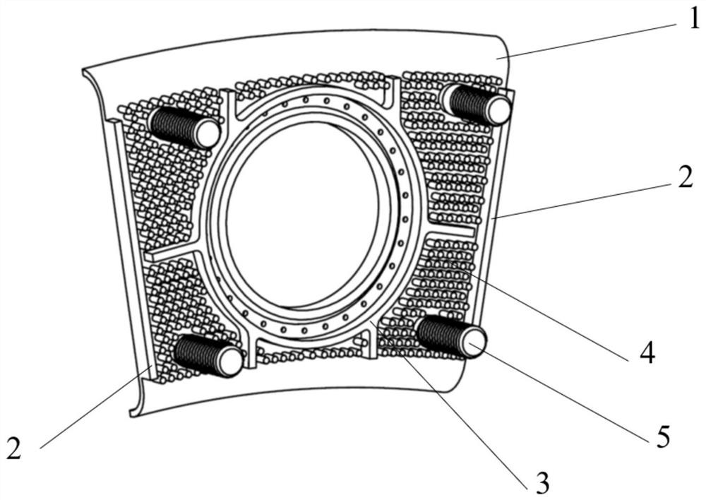
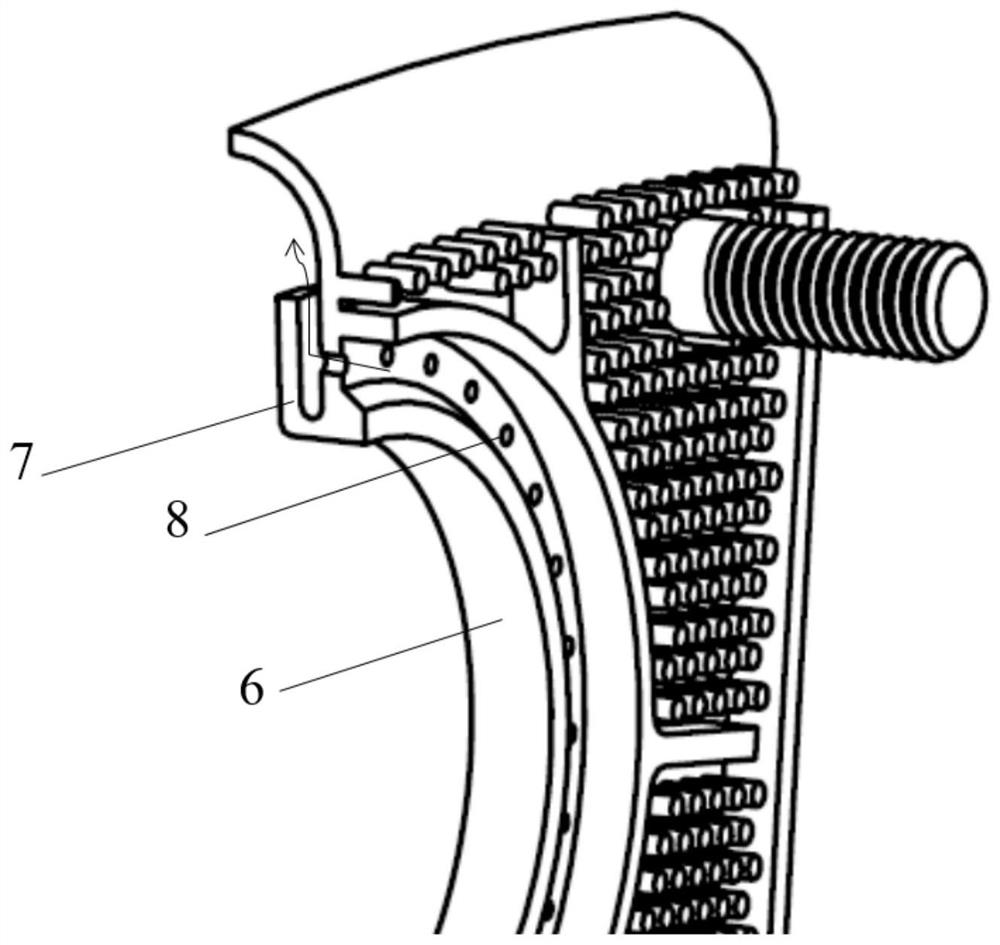
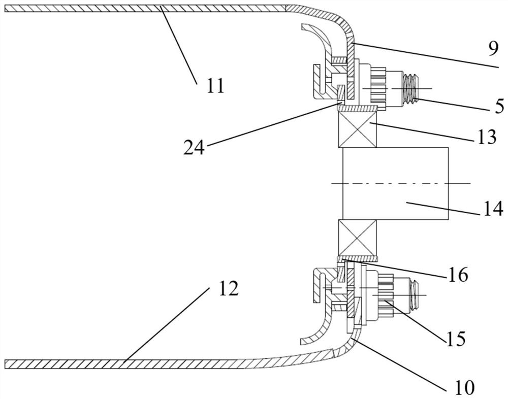
[0034]In order to make the objectives, technical solutions and advantages of the present invention clearer, the technical solutions in the embodiments of the present invention will be described in more detail below in conjunction with the drawings in the embodiments of the present invention. In the drawings, the same or similar reference numerals denote the same or similar elements or elements having the same or similar functions throughout. The described embodiments are some, but not all, embodiments of the invention. The embodiments described below by referring to the figures are exemplary and are intended to explain the present invention and should not be construed as limiting the present invention. Based on the embodiments of the present invention, all other embodiments obtained by persons of ordinary skill in the art without creative efforts fall within the protection scope of the present invention. The structure and technical solutions of the present invention will be f...


PUM


Abstract

The invention relates to an efficient cooling structure of a flame tube head. The structure can be applied to head cooling of combustion chambers of gas turbines and aero-engines, and a flow guide plate is of an integrated structure and comprises a flow guide plate base plate, columnar protrusions, cooling airflow holes, straight ribs on the left side and the right side, a central circular rib, connecting pieces and the like. The flow guide plate is installed on a flame tube head end plate through the connecting pieces, cold air entering from a flame tube flows through the gaps between the columnar protrusions, the gaps between the columnar protrusions and the ribs and the gaps between the columnar protrusions and the connecting pieces, air flow bypasses the multiple columnar protrusions and efficiently cools the flow guide plate and the flame tube head through the gaps, and the wall surface temperature is reduced. The flow guide plate in the structure is simple in structure and can beformed through casting or additive manufacturing printing, compared with a traditional flame tube head flow guide plate structure, the heat exchange area is obviously increased, and the service lifeof the flame tube head and the flow guide plate can be obviously prolonged.

Description

technical field [0001] The invention belongs to the technical field of aero-engines and gas turbine combustion chambers, and in particular relates to a high-efficiency cooling structure for the head of a flame tube. Background technique [0002] With the increasingly stringent environmental protection regulations, in order to achieve low emission targets, civil aero engines and ground gas turbines mostly adopt lean-burn mode in the combustion chamber, that is, the intake air volume entering the combustion chamber from the head of the flame tube increases significantly, and the air intake at the head The air volume accounts for 40% to 60% of the total gas volume in the combustion chamber, which is significantly improved compared with the traditional combustion chamber; and for military engines with high thrust-to-weight ratio, with the increase of the oil-gas ratio, the intake air volume at the head of the combustion chamber will even increase. Reach 70-75%. This means that ...

Claims


Application Information

Patent Timeline
Patent Type & Authority Applications(China)
IPC IPC(8): F23R3/42
CPCF23R3/42F23R2900/03043
Inventor 刘富强王凯兴杨金虎穆勇刘存喜阮昌龙王少林徐纲
Owner INST OF ENGINEERING THERMOPHYSICS - CHINESE ACAD OF SCI
Why Eureka
Try Eureka