Power transformation part secondary equipment real-time state monitoring and automatic defect processing system
A secondary equipment, real-time status technology, applied in the direction of electrical digital data processing, data processing power supply, hardware monitoring, etc., can solve the problems of reducing the safety level of the power grid and the automation level of the power grid, and achieve the effect of reducing the frequency of failures
- Summary
- Abstract
- Description
- Claims
- Application Information
AI Technical Summary
Problems solved by technology
Method used
Image

Examples
Embodiment 1
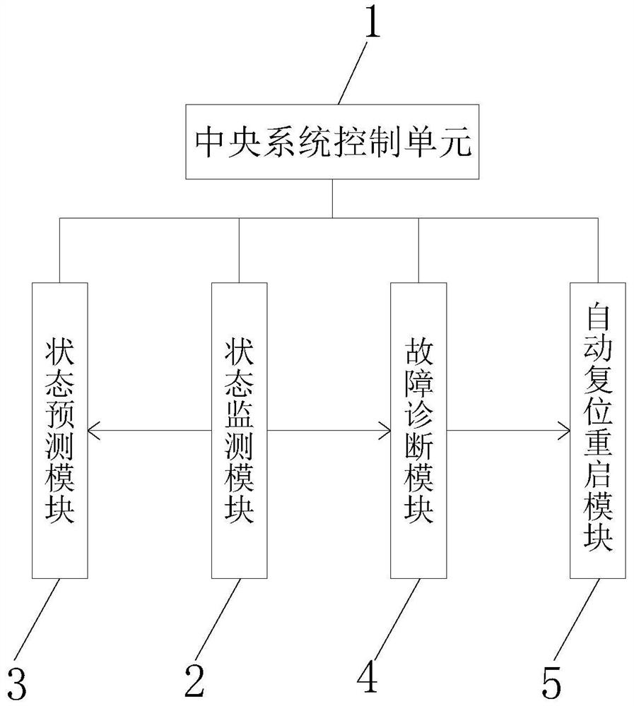
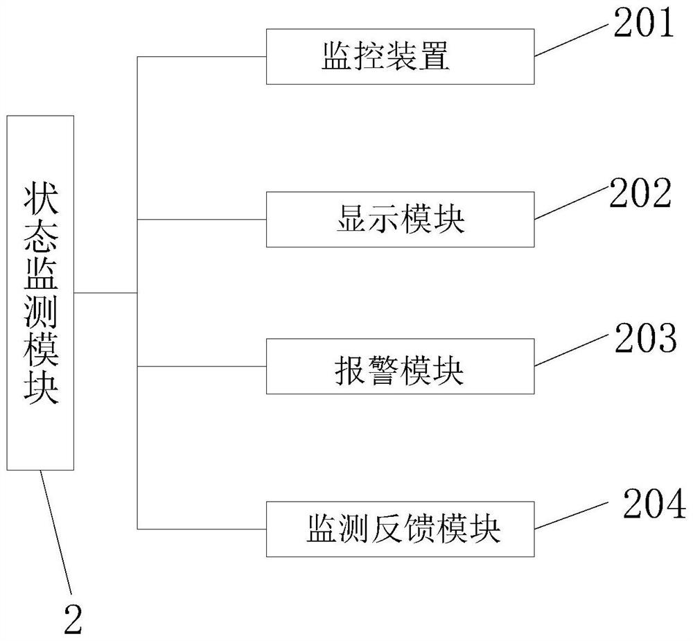
[0028] see Figure 1-Figure 2 , the present invention provides a technical solution: a system for real-time status monitoring and automatic defect processing of secondary equipment in substation parts, including a central system control unit 1, a reset interface 6 and a power circuit 7, and the central system control unit 1 includes a status monitoring module 2. The state prediction module 3, the fault diagnosis module 4 and the automatic reset and restart module 5, the central system control unit 1 is used to electrically connect the state monitoring module 2, the state prediction module 3, the fault diagnosis module 4 and the automatic reset and restart module 5, the central The system control unit 1 is used to control its work, the state monitoring module 2 is electrically connected to the state prediction module 3 and the fault diagnosis module 4, the state monitoring module 2 is used for real-time monitoring of the equipment, and the state monitoring module 2 is the state ...
Embodiment 2
[0031] Such as Figure 4 As shown, on the basis of Embodiment 1, the present invention provides a technical solution: the state prediction module 3 includes a comprehensive capture module 301, a large data storage module 302, a data analysis module 303, a supplementary inspection module 304, and a prediction feedback module 305, The comprehensive capture module 301 is electrically connected to the big data storage module 302, and the big data storage module 302 is electrically connected to the data analysis module 303. Carry out data storage, analyze big data through the data analysis module 303, the data analysis module 303 is electrically connected with the supplementary inspection module 304, the data analysis module 303 is electrically connected with the prediction feedback module 305, and the status of multiple times is performed through the data analysis module 303 Predictions, followed by multiple checks by the supplemental check module 304 to make the data more accurat...
Embodiment 3
[0034] Such as Figure 5 As shown, on the basis of Embodiment 1 and Embodiment 2, the present invention provides a technical solution: the fault diagnosis module 4 includes a monitoring and analysis module 401, a node judgment module 402, a step-by-step investigation module 403 and a fault feedback module 404, and the monitoring and analysis The module 401 is connected with the signal of the node judgment module 402, and the key nodes are judged by analyzing the monitoring data, and the step-by-step investigation module 403 is connected with the signal of the node judgment module 402, and the node judgment module 402 is electrically connected with the reset interface 6 and the power circuit 7, through The fixed device reset interface 6 and the power circuit 7 are used to judge the fault, and the fault is fed back to the central system control unit 1 through the fault feedback module 404 signal-connected to the step-by-step troubleshooting module 403 .
[0035] In this embodime...
PUM
 Abstract
Description
Claims
Application Information
 - R&D
- Intellectual Property
- Life Sciences
- Materials
- Tech Scout
- Unparalleled Data Quality
- Higher Quality Content
- 60% Fewer Hallucinations
Browse by: Latest US Patents, China's latest patents, Technical Efficacy Thesaurus, Application Domain, Technology Topic, Popular Technical Reports.
© 2025 PatSnap. All rights reserved.Legal|Privacy policy|Modern Slavery Act Transparency Statement|Sitemap|About US| Contact US: help@patsnap.com