Vehicle acceleration demand power determination method and device, electronic equipment and storage medium

A technology for accelerating demand and determining methods, which is applied in the fields of electrical digital data processing, design optimization/simulation, and special data processing applications, etc., and can solve problems such as large labor costs, low work efficiency, and failure to consider the entire vehicle

Active Publication Date: 2021-03-12
ZHEJIANG GEELY HLDG GRP CO LTD +4
View PDF7 Cites 0 Cited by
  • Summary
  • Abstract
  • Description
  • Claims
  • Application Information

AI Technical Summary

Problems solved by technology

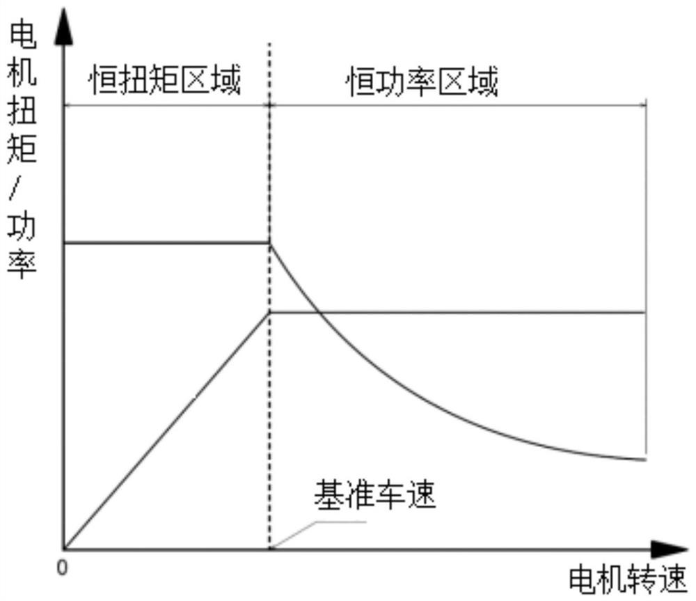
However, in reality, for most motor-driven vehicles, the transmission system of the vehicle only has a single-stage transmission mechanism, and the motor has the characteristics of constant torque and constant power work area division, which cannot guarantee that the vehicle is always in an equal power driving state
Therefore, the traditional calculation method uses the average power of the acceleration process to replace the required power of the vehicle, without considering the change process of the actual driving power of the vehicle, and the calculation results often cannot meet the requirements of the vehicle acceleration performance index
[0005] In addition, the traditional calculation method is to input the motor parameters into the dynamic simulation software for virtual verification to avoid insufficient design of the motor, such as AVL cruise software, but this method requires repeated modification and adjustment of the motor input parameters, although it can achieve a balance between performance and cost effect, but the work efficiency is low, it is blind, and the labor cost is large

Method used

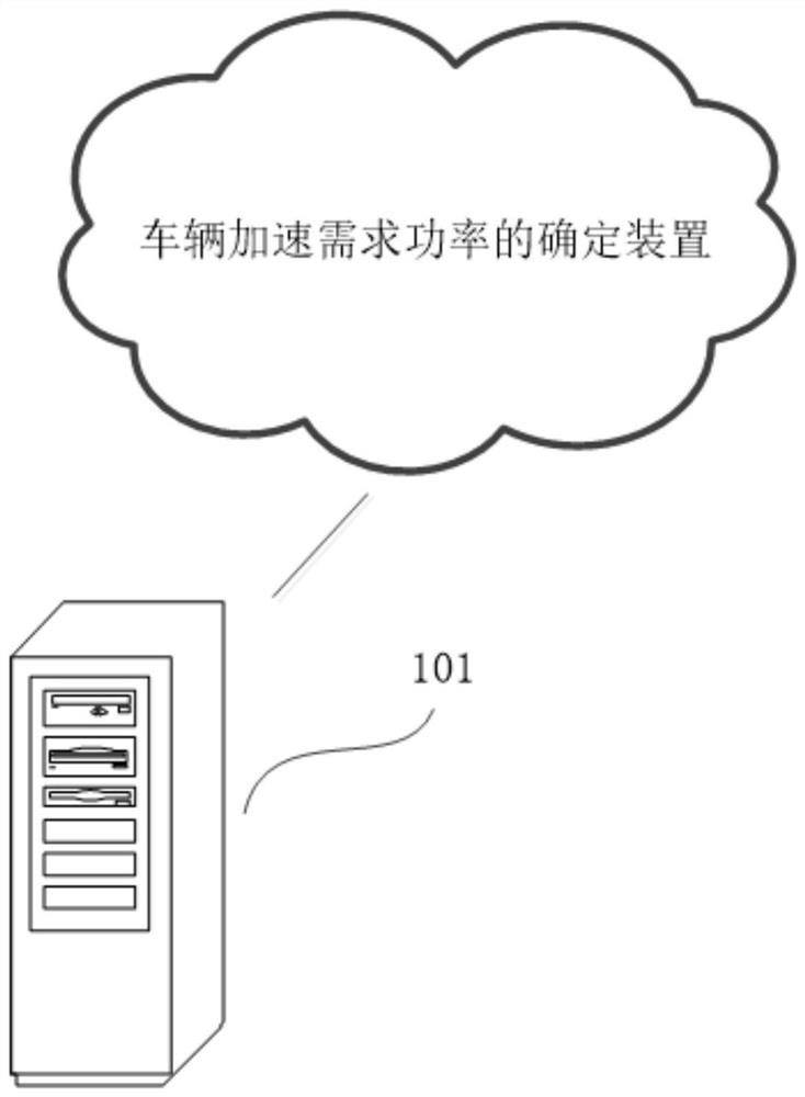
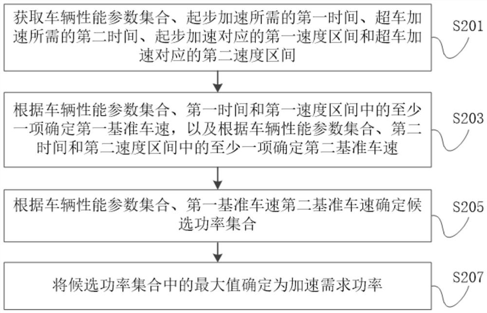

Image

  • Vehicle acceleration demand power determination method and device, electronic equipment and storage medium
  • Vehicle acceleration demand power determination method and device, electronic equipment and storage medium
  • Vehicle acceleration demand power determination method and device, electronic equipment and storage medium

Examples


Embodiment Construction

[0057] In order to make the purpose, technical solution and advantages of the present application clearer, the embodiments of the present application will be further described in detail below in conjunction with the accompanying drawings. Apparently, the described embodiment is only one embodiment of the present application, rather than all the embodiments. Based on the embodiments in this application, all other embodiments obtained by persons of ordinary skill in the art without creative efforts fall within the protection scope of this application.

[0058] The "embodiment" referred to herein refers to a specific feature, structure or characteristic that may be included in at least one implementation of the present application. In the description of the embodiments of the present application, it should be understood that the terms "first", "second", "third", "fourth" and "fifth" are used for descriptive purposes only, and should not be interpreted as indicating Either imply ...


PUM


Abstract

The embodiment of the invention discloses a vehicle acceleration demand power determination method and device, electronic equipment and a storage medium, and the method comprises the steps: obtaininga vehicle performance parameter set, first time needed by starting acceleration, second time needed by overtaking acceleration, a first speed interval corresponding to starting acceleration, and a second speed interval corresponding to overtaking acceleration; determining a first reference vehicle speed according to at least one of the vehicle performance parameter set, the first time and the first speed interval, and determining a second reference vehicle speed according to at least one of the vehicle performance parameter set, the second time and the second speed interval, and determining acandidate power set according to the vehicle performance parameter set, the first reference vehicle speed and the second reference vehicle speed, and determining the maximum value in the candidate power set as acceleration demand power. The task of determining the acceleration demand power is converted into the task of determining the reference vehicle speed of the motor so as to establish the unary cubic equation, the calculation process can be simplified, and the calculation cost can be reduced.

Description

technical field [0001] The invention relates to the field of motor parameter development and design, in particular to a method, device, electronic equipment and storage medium for determining the required power for vehicle acceleration. Background technique [0002] New energy vehicles are the main direction of future automobile development. Although there are differences in energy types and energy supply methods for new energy vehicles, motor drive is the main driving mode of various technical routes. According to the needs of complete vehicles, major automobile manufacturers are accelerating investment in new In the development and layout of energy products, choose a matching or develop a motor reasonably. When the power of the drive motor is insufficient, the power performance of the vehicle will not meet the standard. When the power of the drive motor is too high, it will bring the cost of the drive system. The increase is not conducive to the market competitiveness of p...

Claims


Application Information

Patent Timeline
Patent Type & Authority Applications(China)
IPC IPC(8): G06F30/15G06F30/20G06F16/2455
CPCG06F30/15G06F30/20G06F16/2455Y02T10/72
Inventor 朱龙锋王荣华崔俊博贺子龙王多衎刘中拥李楠
Owner ZHEJIANG GEELY HLDG GRP CO LTD
Why Eureka
Try Eureka