Continuous casting billet surface pit defect identification method

A pit defect and identification method technology, applied in image data processing, instruments, calculations, etc., can solve problems such as increased risk factor, easy cracks, pits, increased loss of nickel-based steel, etc., to eliminate safety risks, data Comprehensive and specific, the effect of improving the safety index

Pending Publication Date: 2021-03-12
NANJING IRON & STEEL CO LTD
View PDF11 Cites 4 Cited by
  • Summary
  • Abstract
  • Description
  • Claims
  • Application Information

AI Technical Summary

Problems solved by technology

[0002] Before the nickel-based steel continuous casting slab enters the heating furnace for rolling, it generally removes pits, cracks and other defects on the surface by grinding. Because the depth of the pits is different, the pits cannot be completely removed due to too little grinding. Defects such as cracks and pits are prone to occur during the manufacturing process, and excessive grinding will increase the loss of nickel-based steel
[0003] Generally, the surface pits after continuous casting grinding are manually counted. Because there are large-scale equipment in operation and moving vehicles on the grinding site, these increase the risk factor for the statisticians. In addition, the grinding interval is longer, which increases the time cost.

Method used


Image

  • Continuous casting billet surface pit defect identification method
  • Continuous casting billet surface pit defect identification method

Examples


Embodiment Construction

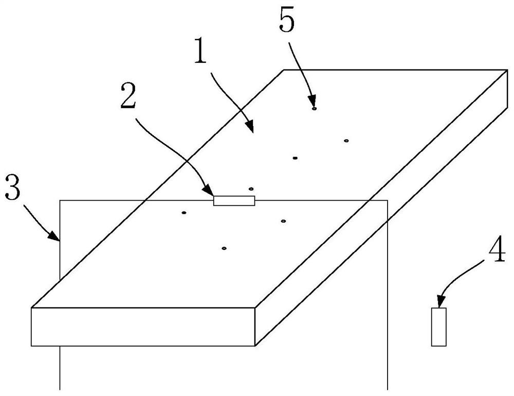
[0025] Such as figure 1 , 2 As shown, the 3D camera 2 is fixed above the ground roller table through the bracket 3 before the implementation of the pit defect identification method on the surface of the continuous casting slab, and the position, direction and angle of the visual inspection remain unchanged.

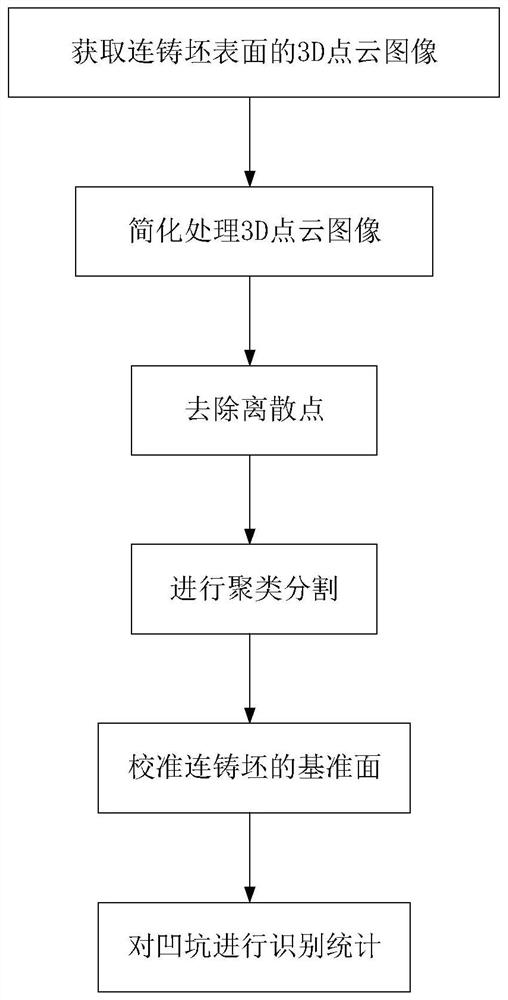
[0026] The identification steps include:

[0027] (1) Use the 3D camera 2 to photograph the surface of the continuous casting slab 1 after grinding, and obtain the 3D point cloud image of the continuous casting slab;

[0028] Specifically, when the grinding is completed, the continuous casting slab 1 advances to the visual detection position, and when the photoelectric sensor 4 detects the incoming signal of the continuous casting slab 1, the 3D camera 2 is triggered to take pictures, and the continuous casting slab point cloud image in PCD format is obtained.

[0029] (2) Use the downsampling algorithm to simplify the 3D point cloud image;

[0030] This function creat...


PUM


Abstract

The invention discloses a continuous casting billet surface pit defect identification and statistics method, which adopts 3D vision to identify pits and depths of the pits in a continuous casting billet polishing process so as to realize automatic statistics of the number of the pits. On the one hand, the method can replace manual on-site pit identification statistics, save labor cost, eliminate safety risks and improve on-site safety indexes; on the other hand, continuous real-time identification statistics can be realized, the counting efficiency is improved, the acquired data is more comprehensive and specific, and data support is provided for continuous casting process improvement.

Description

technical field [0001] The invention relates to a method for judging surface quality, in particular to a method for identifying pit defects on the surface of continuous casting slabs. Background technique [0002] Before the nickel-based steel continuous casting slab enters the heating furnace for rolling, it generally removes pits, cracks and other defects on the surface by grinding. Because the depth of the pits is different, the pits cannot be completely removed due to too little grinding. Defects such as cracks and pits are prone to occur during the manufacturing process, and excessive grinding will increase the loss of nickel-based steel. [0003] Generally, the surface pits after continuous casting grinding are manually counted. Because there are large-scale equipment in operation and moving cranes on the grinding site, these increase the risk factor for the statisticians. In addition, the grinding interval is longer, which increases the time cost. Contents of the in...

Claims


Application Information

Patent Timeline
Patent Type & Authority Applications(China)
IPC IPC(8): G06T7/00G06T7/11G06T7/187G06T7/60
CPCG06T7/0004G06T7/11G06T7/187G06T7/60G06T2207/30136G06T2207/10028
Inventor 代芹芹蔡佳兴范益杨文秀
Owner NANJING IRON & STEEL CO LTD
Why Eureka
Try Eureka