
Method and device for measuring distance between power transmission line and target object, and electronic equipment

A transmission line and distance measurement technology, which is applied in the field of transmission network, can solve the problems of large measurement error and inability to monitor transmission lines around the clock, and achieve the effect of improving accuracy and accurate results

Pending Publication Date: 2021-03-12
STATE GRID JIANGSU ELECTRIC POWER CO LTD TAIZHOU POWER SUPPLY BRANCH
View PDF0 Cites 8 Cited by
  • Summary
  • Abstract
  • Description
  • Claims
  • Application Information

AI Technical Summary

Problems solved by technology

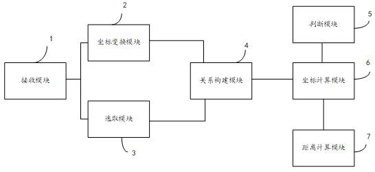
[0004] The invention provides a method, device and electronic equipment for measuring the distance between a power transmission line and a target object, which can solve the problem that the traditional hand-held laser range finder has a large measurement error and cannot monitor the power transmission line all-weather

Method used


Image

  • Method and device for measuring distance between power transmission line and target object, and electronic equipment
  • Method and device for measuring distance between power transmission line and target object, and electronic equipment
  • Method and device for measuring distance between power transmission line and target object, and electronic equipment

Examples


Embodiment Construction

[0056] In order to better understand the above technical solutions, the above technical solutions will be described in detail below with reference to the accompanying drawings and specific embodiments.

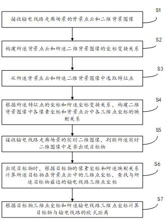
[0057] refer to figure 1 , in some embodiments, a method for measuring the distance between a power transmission line and a target is provided, comprising:

[0058] S1. Receive the background point cloud and two-dimensional background image of the transmission line corridor scene;

[0059] S2, constructing the coordinate transformation relationship between the background point cloud and the two-dimensional background image;

[0060] S3, select feature points from the background point cloud and the two-dimensional background image;

[0061] S4, according to the coordinates of the feature points and the coordinate transformation relationship, build a mapping relationship between the coordinates of each pixel in the two-dimensional background image and the coordinates of each t...


PUM


Abstract

The invention discloses a method and device for measuring the distance between a power transmission line and a target object, and electronic equipment. The method comprises the steps: receiving background point cloud and a two-dimensional background image of a corridor scene of the power transmission line; constructing a coordinate transformation relationship between the background point cloud andthe two-dimensional background image; selecting feature points from the background point cloud and the two-dimensional background image to construct a mapping relationship between each pixel coordinate in the two-dimensional background image and each three-dimensional point coordinate in the background point cloud; receiving a real-time two-dimensional image of the power transmission line corridor scene, and judging whether a target object appears in the real-time two-dimensional image or not; when the target object appears, calculating the three-dimensional point coordinates of the target object in the background point cloud according to the pixel coordinates of the target object and the mapping relationship, and searching the three-dimensional point coordinates of the power transmissionline closest to the target object; and calculating the Euclidean distance between the target object and the power transmission line according to the three-dimensional point coordinates of the targetobject and the three-dimensional point coordinates of the power transmission line. The method can solve the problem that the measurement mode of a traditional handheld laser range finder is large in error.

Description

technical field [0001] The present application relates to the technical field of power transmission networks, and in particular, to a method, device and electronic device for measuring the distance between a power transmission line and a target. Background technique [0002] The traditional method is to measure the distance of the transmission line by using artificial ground laser ranging. The inspector uses a handheld laser rangefinder to measure the distance between the target and the transmission line. The basic principle of this method is to use the flight of light. Time, distance is calculated from the speed of light and the coefficient of refraction of the atmosphere. [0003] The measurement method of traditional hand-held laser rangefinders is easily interfered and influenced by human and environmental factors. For example, in areas with more sunny days, the infrared rays contained in the strong sunlight will cause a large measurement error for the handheld laser ra...

Claims


Application Information

Patent Timeline
IPC IPC(8): G06T7/73G06K9/00G06K9/62G01C3/00
CPCG06T7/73G01C3/00G06T2207/10028G06V20/52G06F18/24
Inventor 戴永东王茂飞毛锋余万金蒋中军邵杰贾俊翁蓓蓓鞠玲
Owner STATE GRID JIANGSU ELECTRIC POWER CO LTD TAIZHOU POWER SUPPLY BRANCH
Learn More