
Differential pressure damping type protection method and device for self-healing capacitor

A protection device and capacitor technology, applied in capacitors, laminated capacitors, wire wound capacitors, etc., can solve the problems of high internal pressure of capacitors, internal pressure explosion and ignition, huge discharge current, etc., and achieve stable and accurate action values. Accurate and reliable action , to ensure the effect of safe operation

Active Publication Date: 2021-03-12
武汉电联电力电气技术有限公司
View PDF4 Cites 2 Cited by
  • Summary
  • Abstract
  • Description
  • Claims
  • Application Information

AI Technical Summary

Problems solved by technology

This method exists: 1) The internal pressure of the capacitor is affected by the operating temperature. When the temperature is high, the internal pressure of the capacitor is high, and when the temperature is low, the capacitor pressure is low.
Therefore, the patented technology is prone to misoperation in application; 2) the patent can only complete the action when the deformation of the capacitor shell is large enough, and the capacitor is prone to explosion at this time
3) This patent does not consider that when the two poles are short-circuited, a huge discharge current will be generated to cause explosion
Therefore, the external circuit cannot be detected, and it is difficult to take the capacitor out of operation. However, due to excessive self-healing of the faulty capacitor element at this time, it is easy to cause an explosion and fire accident due to excessive internal pressure or high temperature.

Method used


Image

  • Differential pressure damping type protection method and device for self-healing capacitor
  • Differential pressure damping type protection method and device for self-healing capacitor
  • Differential pressure damping type protection method and device for self-healing capacitor

Examples


Embodiment Construction

[0037] The technical solution of the present invention will be further described below in conjunction with the accompanying drawings.

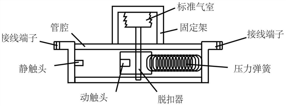
[0038] like image 3 and Figure 4 As shown, a self-healing capacitor differential pressure damping protection device of the present invention includes a trigger device, a lumen, two terminals, a static contact, a moving contact, a release and a pressure spring, and the two ends of the lumen are respectively arranged Two terminals, one of which is connected to the static contact, the other terminal is connected to the pressure spring, the static contact and the pressure spring are respectively fixed at both ends of the lumen, the other side of the pressure spring is connected to the moving contact, the pressure The spring is stuck in the lumen through the release device. If the release device falls off, the pressure spring will push forward to make the moving contact and the static contact connected, so that the electrical performance of the ...


PUM


Abstract

The invention relates to the field of high-voltage protection, in particular to a differential pressure damping type protection method and device for a self-healing capacitor. According to the methodprovided by the invention, temperature compensation is realized and the pressure inside the capacitor is detected through an independent standard air chamber, once the difference between the pressureand the pressure of the standard air chamber reaches a set value, the standard air chamber is compressed to enable the release to be in a release state, and the moving contact is pushed by the energystorage spring to be closed with the static contact; and a capacitor connected in parallel with the capacitor is short-circuited. In order to limit the discharge current of the capacitor to be overlarge, a damper is connected in the action process, the discharge current is reduced, and secondary faults are avoided. The two poles of the capacitor are short-circuited, so that the faulty capacitor does not bear voltage any more, further development of faults is avoided, meanwhile, an external protection circuit can accurately and reliably detect faults of the capacitor device, the faulty capacitor can quit operation in time, and the purpose of avoiding fault expansion is achieved.

Description

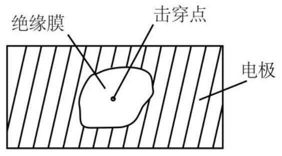
technical field [0001] The invention relates to the field of high voltage protection, in particular to a self-healing capacitor pressure difference damping protection method and device. Background technique [0002] The self-healing power capacitor is composed of a metallized film with a very thin metal electrode evaporated on the insulating film. When there is a weak point on the insulating film and a breakdown occurs, the charge stored in the capacitor will flow to the shock. The breakthrough point surges, and a huge current density is generated on the electrode near the breakdown point, so that a small piece of electrode layer near the breakdown point is vaporized instantly (usually ≤0.1ms), and the breakdown point is restored from the short circuit state to Insulation state (see the attached figure 1 ), this process is called self-healing. During the self-healing process, part of the metal electrodes and insulating materials will be vaporized by the high temperature ge...

Claims


Application Information

Patent Timeline
IPC IPC(8): H01G4/33H01G4/32H01G4/38H01G4/258H01G2/18H01H71/16G01L13/00
CPCH01G4/33H01G4/32H01G4/385H01G4/258H01G2/18H01H71/16G01L13/00Y02E40/30
Inventor 倪明珏雷莎刘瑞云
Owner 武汉电联电力电气技术有限公司
Learn More