
Refining mechanism for mining machinery

A homogenizing mechanism and mechanical technology, which is applied in the direction of mixers, mixer accessories, shaking/oscillating/vibrating mixers, etc., can solve the problems of inability to ensure uniform mixing of mineral materials, reduce dust pollution and inhalable particulate matter, etc.

Inactive Publication Date: 2021-03-16
LOUDI DINGHONG AUTOMATION EQUIP
View PDF1 Cites 0 Cited by
  • Summary
  • Abstract
  • Description
  • Claims
  • Application Information

AI Technical Summary

Problems solved by technology

[0003] After retrieval, Chinese Patent No. CN211026520U discloses a mining machinery leveling mechanism, which realizes primary pulverization through the pulverizing shaft and the pulverizing shaft, and realizes secondary pulverization through the pulverizing shaft and the pulverizing shaft, so as to achieve uniform particle size during homogenization. At the same time, the design of the air inlet pipe, the upper cover plate and the dust removal box is convenient for removing the dust generated during the operation of the equipment, and has the effect of reducing dust pollution and inhalable particulate matter, which is beneficial to protect the health of the operator, and the material ore passes through the diode. After being crushed, it enters the homogenizing box, and is discharged from the outlet after being stirred by the stirring rod, so as to realize the effect of crushing, dust removal and stirring in one during the ore homogenizing process, but when the ore is homogenized by this homogenizing mechanism, Unable to ensure uniform mixing between mineral materials

Method used


Image

  • Refining mechanism for mining machinery
  • Refining mechanism for mining machinery
  • Refining mechanism for mining machinery

Examples


Embodiment Construction

[0024] The following will clearly and completely describe the technical solutions in the embodiments of the present invention with reference to the accompanying drawings in the embodiments of the present invention. Obviously, the described embodiments are only some, not all, embodiments of the present invention. Based on the embodiments of the present invention, all other embodiments obtained by persons of ordinary skill in the art without making creative efforts belong to the protection scope of the present invention.

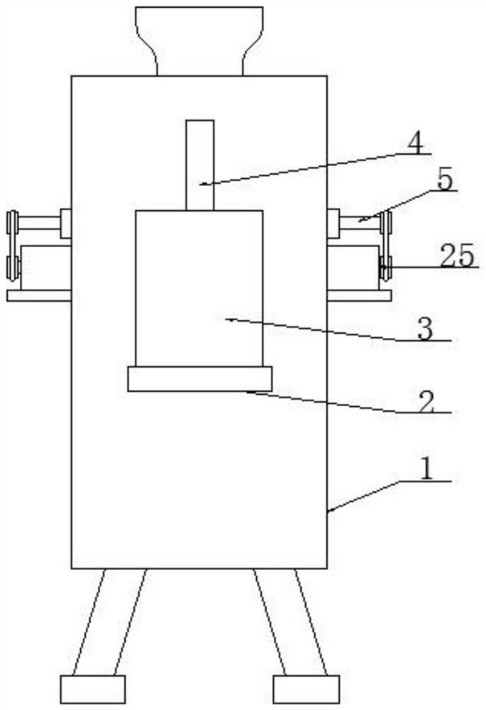
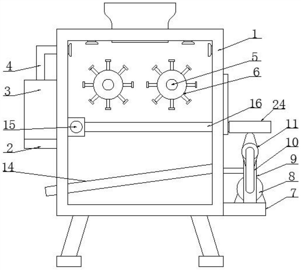
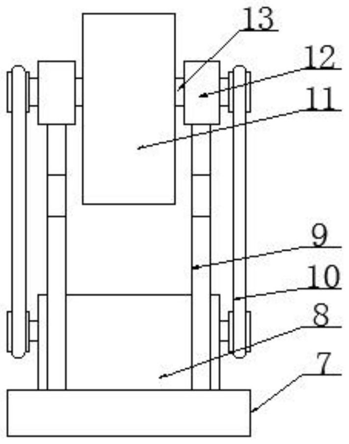
[0025] see Figure 1-6 , a mining machinery leveling mechanism, including a box body 1, the two sides of the box body 1 are respectively fixedly installed with a first support plate 2, a second support plate 7 and a power mechanism 25, and the top of the first support plate 2 is fixedly installed with Suction fan 3, pipeline 4 is fixedly installed on the top of suction fan 3, motor 8 and support column 9 are fixedly installed on the top of the second support p...


PUM


Abstract

The invention relates to the technical field of mining equipment, and discloses a refining mechanism for mining machinery. The refining mechanism comprises a box body, a first support plate, a secondsupport plate and a power mechanism are fixedly mounted on the two sides of the box body correspondingly, a suction fan is fixedly mounted at the top of the first support plate, and a pipeline is fixedly mounted at the top of the suction fan. According to the refining mechanism for mining machinery, the power mechanism drives a first rotating shaft to drive an overturning roller to rotate, mineralaggregate in the box body is driven to overturn when the overturning roller rotates, when the mineral aggregate is located on a vibrating plate, a motor rotates to drive a transmission belt to rotatethrough an output shaft, the transmission belt drives a cam to rotate through a second rotating shaft while rotating, the cam rotates to drive a connecting plate to vibrate up and down, and the connecting plate is fixedly connected with the vibrating plate, so that the vibrating plate can also vibrate up and down, the mineral aggregate in the box body can vibrate up and down and turn over, and the purpose of uniformly mixing the mineral aggregate is achieved.

Description

technical field [0001] The invention relates to the technical field of mining equipment, in particular to a mining machinery leveling mechanism. Background technique [0002] Homogenizer is an earlier traditional mechanical product used for mixing various raw materials. Widely used in metallurgical industry, mining machinery and building materials and other fields. The homogenizer is a widely used raw material mixing machine. In the fields of mining and metallurgy, the homogenizer is also widely used in raw material mixing. [0003] After retrieval, Chinese Patent No. CN211026520U discloses a mining machinery leveling mechanism, which realizes primary pulverization through the pulverizing shaft and the pulverizing shaft, and realizes secondary pulverization through the pulverizing shaft and the pulverizing shaft, so as to achieve uniform particle size during homogenization. At the same time, the design of the air inlet pipe, the upper cover plate and the dust removal box i...

Claims


Application Information

Patent Timeline
IPC IPC(8): B01F13/10B01F7/04B01F11/00B01F15/00B01F15/02
CPCB01F27/701B01F31/00B01F31/70B01F33/82B01F35/184B01F35/75
Inventor 肖永忠
Owner LOUDI DINGHONG AUTOMATION EQUIP
Learn More