Ultrasonic atomization pyrolysis spraying device and spraying method

A technology of ultrasonic atomization and spraying mechanism, applied in spraying device, liquid spraying device, chemical instrument and method, etc., can solve the problems of difference in chemical properties, poor functionality, speed up the research and development process of new materials, etc., to achieve good performance, prevent Scratching, the effect of convenient atomization spraying work

Pending Publication Date: 2021-03-16
绍兴权电科技有限公司
View PDF9 Cites 2 Cited by
  • Summary
  • Abstract
  • Description
  • Claims
  • Application Information

AI Technical Summary

Problems solved by technology

These materials are usually composed of binary or higher elements. The composition and structure of materials are different, which often leads to huge differences in various physical and chemical properties of materials. The emergence of high-throughput composite material chip technology can greatly Accelerate the research and development process of new materials, and complete the work of traditional "trial and error" for months or even years in a relatively short period of time. The core of this technology is to rely on physical vapor deposition technology, chemical vapor deposition technology or solid sintering method Prepare up to 106 samples of different components on the linch substrate, and rely on high-throughput characterization technology to perform parallel or scanning detection on the prepared high-throughput sample library. High-performance thin-film materials need to be sprayed during production However, the existing spraying device can only complete the spraying effect, so when used, there are certain limitations and poor functionality

Method used


Image

  • Ultrasonic atomization pyrolysis spraying device and spraying method
  • Ultrasonic atomization pyrolysis spraying device and spraying method
  • Ultrasonic atomization pyrolysis spraying device and spraying method

Examples


Embodiment Construction

[0030]The technical solutions in the embodiments of the present invention will be clearly and completely described below with reference to the accompanying drawings in the embodiments of the present invention. Obviously, the described embodiments are only a part of the embodiments of the present invention, but not all of the embodiments. Based on the embodiments of the present invention, all other embodiments obtained by those of ordinary skill in the art without creative efforts shall fall within the protection scope of the present invention.

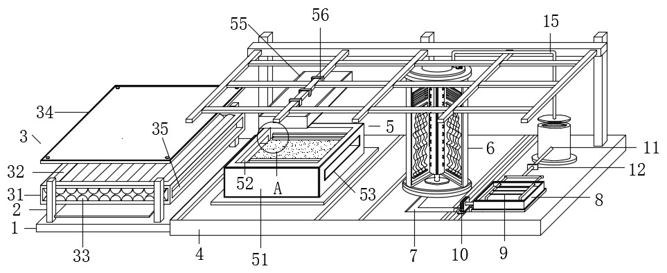
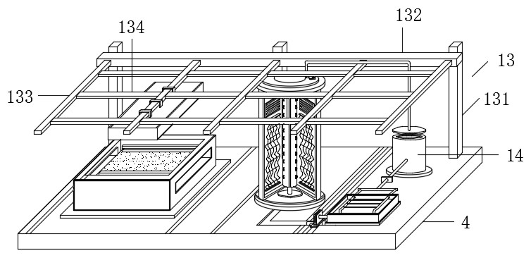
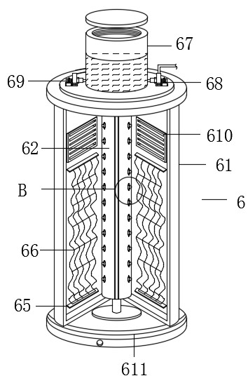
[0031] see Figure 1-7 , the present invention provides a technical solution: an ultrasonic atomization pyrolysis spraying device, comprising a No. 1 base plate 1, a conveying mechanism 3, a No. 2 base plate 4, a spraying mechanism 5, a cleaning mechanism 6, a pipe box 8 and a bracket mechanism 13, The four corners of the upper surface of the No. 1 base plate 1 are fixedly installed with support columns 2 through fixing bolts, the conv...


PUM


Abstract

The invention discloses an ultrasonic atomization pyrolysis spraying device and a spraying method. The ultrasonic atomization pyrolysis spraying device comprises a first bottom plate, a conveying mechanism, a second bottom plate, a spraying mechanism, a cleaning mechanism, a pipeline box and a support mechanism, supporting columns are fixedly installed at the four corners of the upper surface of the first bottom plate through fixing bolts, and the conveying mechanism is fixedly installed among the four supporting columns. The second bottom plate is fixedly installed on the outer wall of one side of the first bottom plate, the spraying mechanism is fixedly installed on one side of the upper surface of the second bottom plate, and the cleaning mechanism is fixedly installed on the other sideof the upper surface of the second bottom plate. The ultrasonic atomization pyrolysis spraying device and the spraying method have the beneficial effects that according to the ultrasonic atomizationpyrolysis spraying device, through the cooperation use of each structure, the conveying, spraying and cleaning work can be conveniently completed, the device can integrate automatic conveying, automatic spraying, automatic cleaning and automatic drying, has good functionality, multiple functions, a simple structure and a high spraying effect, can complete water recycling of the whole device, improves the resource utilization rate, and is suitable for popularization and application.

Description

technical field [0001] The invention relates to the technical field of spraying, in particular to an ultrasonic atomization pyrolysis spraying device. Background technique [0002] High-performance thin-film materials have very important applications in the fields of modern communication technology, optoelectronic technology, photocatalysis, new energy, aviation and national defense. These materials are usually composed of binary and above elements. The composition and structure of the materials are different, which often lead to huge differences in various physical and chemical properties of the materials. The emergence of high-throughput composite material chip technology can greatly It accelerates the research and development process of new materials, and can complete the traditional "trial and error method" months or even years in a relatively short time. The core of this technology is to rely on physical vapor deposition technology, chemical vapor deposition technology ...

Claims


Application Information

Patent Timeline
Patent Type & Authority Applications(China)
IPC IPC(8): B05B16/20B05B17/06B05B15/00B05B13/02B05D3/04B08B3/02
CPCB05B13/0221B05B15/00B05B17/06B05D3/0413B08B3/02B05B16/20
Inventor 覃永波
Owner 绍兴权电科技有限公司
Why Eureka
Try Eureka