Multi-station laser de-insulation fixing device

A fixing device and de-insulation technology, which is applied in the field of multi-station laser de-insulation and fixing devices, can solve the problems of high manual labor intensity, cumbersome operation process, inconvenient operation of equipment construction, etc., and achieve the goal of reducing labor intensity and facilitating de-insulation work Effect

Pending Publication Date: 2021-03-16
CSR ZHUZHOU ELECTRIC CO LTD
View PDF0 Cites 0 Cited by
  • Summary
  • Abstract
  • Description
  • Claims
  • Application Information

AI Technical Summary

Problems solved by technology

Among them, the manual hand-held fixing method has high labor intensity, and the operation process is cumbersome, and it is not convenient for the construction of the operating equipment; in addition, the use of existing operating equipment for de-insulation work also has the problem of poor insulation removal effect

Method used


Image

  • Multi-station laser de-insulation fixing device
  • Multi-station laser de-insulation fixing device
  • Multi-station laser de-insulation fixing device

Examples


Embodiment Construction

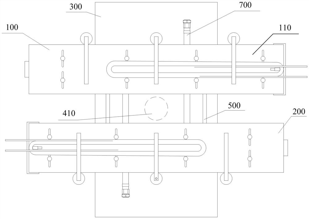
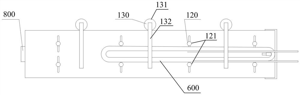
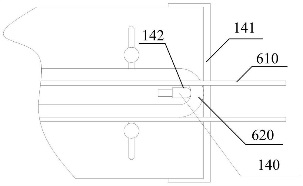
[0039] Aiming at the situation that the operator manually operates the coil, the invention discloses a multi-station laser de-insulation and fixing device. Among them, the present invention uses a pneumatic clamp to clamp the coil, and uses a servo motor to drive the clamp to rotate at a certain angle to drive the coil to rotate, so as to meet the requirements of the laser device for removing insulation on each surface of the coil lead head. On this basis, double stations are also designed, so that the loading and unloading stations and working stations are alternately switched, and the operation is cycled to achieve the purpose of shortening the working time.

[0040] The following will clearly and completely describe the technical solutions in the embodiments of the present invention with reference to the accompanying drawings in the embodiments of the present invention. Obviously, the described embodiments are only some, not all, embodiments of the present invention. Based ...


PUM


Abstract

The invention discloses a multi-station laser de-insulation fixing device which comprises a first station fixing device. The first station fixing device comprises an installing plate used for installing a coil, a coil side face clamp arranged on the installing plate and used for clamping two side faces of the coil, a coil height direction clamp arranged on the installing plate and used for pressing the coil vertically, and a coil nose clamp arranged on the installing plate and used for clamping the coil to be close to a lead head. According to the scheme, by means of the effect of the coil side face clamp, the coil height direction clamp and the coil nose clamp, clamping and fixing of the coil in the width direction and the height direction and on the nose portion are achieved conveniently, thus the fixing manner of manual hand-holding is replaced, and thus labor intensity of an operator is effectively reduced. Meanwhile, a laser device can carry out de-insulation operation more conveniently.

Description

technical field [0001] The invention relates to the technical field of coil de-insulation, in particular to a multi-station laser de-insulation fixing device. Background technique [0002] In order to achieve higher insulation strength, traction motors generally use sintered films or copper or aluminum wires coated with impregnated varnish to make windings. After the windings are embedded, the winding leads need to be welded and connected according to certain principles. Therefore, it is necessary to remove the insulating layer of the magnet wire used for the winding. No matter the copper wire insulation layer is a film, the glue coated on the surface of the film is cured at a certain temperature, so that the film and the copper or aluminum wire are closely bonded together; Together. When producing on site, it is necessary to consider both the reliability of the removal and the operating efficiency, so certain tools or methods must be used to remove the insulating layer. ...

Claims


Application Information

Patent Timeline
IPC IPC(8): B23K26/36B23K26/70B23K37/04
CPCB23K26/36B23K37/04B23K26/702
Inventor 韦在凤粟诗雨李琳浩文思静袁双玲凌翠平那春龙
Owner CSR ZHUZHOU ELECTRIC CO LTD
Why Eureka
Try Eureka