9-axis linkage welding robot with C-shaped cantilever structure

A welding robot and shaft linkage technology, applied in welding equipment, auxiliary welding equipment, welding/cutting auxiliary equipment, etc., can solve the problems of physical hazards of surrounding workers, reduce product use effect, pollute the environment, etc., and achieve good smoke removal effect , Improving the use effect, convenient maintenance and cleaning

Pending Publication Date: 2021-03-16
南京合信自动化有限公司
View PDF0 Cites 0 Cited by
  • Summary
  • Abstract
  • Description
  • Claims
  • Application Information

AI Technical Summary

Problems solved by technology

[0004] At present, there are still deficiencies in the use of existing welding robots. The existing welding robots will produce welding smoke and toxic gases during the welding process. Due to the lack of corresponding smoke removal devices, it will not only pollute the environment, but also cause harm to the surrounding staff. Harm to the body and reduce the effectiveness of the product

Method used


Image

  • 9-axis linkage welding robot with C-shaped cantilever structure
  • 9-axis linkage welding robot with C-shaped cantilever structure
  • 9-axis linkage welding robot with C-shaped cantilever structure

Examples


Embodiment 1

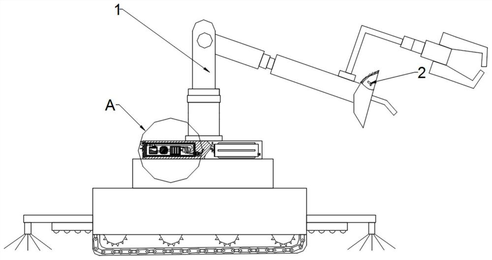
[0042] See figure 1 versus figure 2 A C-type cantilever structure 9 axis linkage welding robot, including welding robot main body 1, and welding robots include:

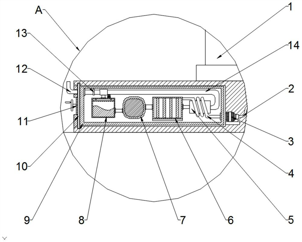
[0043] The transmission pump 3 is fixed to the outer surface wall of the clear hookes main body 9, and the outer surface of the cleavage body 9 is fixed to the welding robot body 1, and the inner surface wall of the clear hook hood is fixedly connected to the exhaust pipe 12, the exhaust pipe 12 The outer wall fixing the electromagnetic valve 13, the outer surface wall of the solenoid valve 13 is fixedly connected to the circulation tube 14, and the circulation tube 14 is fixedly connected to the dry bin 5, the transmission pump 3 transmission ends are connected to the smoking pipe 2, the transmission pump 3 away from smoking pipe 2 One end is connected to the dry tube 4, the outer surface wall of the drying tube 4 is wrapped with the dry bin 5, and the dry bin 5 is fixed to the pipe opening 6, and the filter dust cart...

Embodiment 2

[0047] See Figure 5 versus Figure 6 The inner surface wall of the clear hook hook hood is engaged with the transmission pump 3 by the elastic ring protrusion, the outer wall of the welding robot body 1 is connected to the door 15 through the rotating shaft activity, the interior wall of the hatch 15 is connected to the screw 16 The inner surface wall of the hatch 15 is attached to the clear hook hook body 9, and the inner surface wall of the hatch 15 is fixedly connected to the elastic gasket, and the gap between the fingertips 15 and the cleavage hoses body 9 makes the connection more tightly. The inner surface wall of the cleavage hood body 9 is fixedly connected to the sealing space of the dry tube 4 and the transmission pump 3 in the inner surface wall of the cleaning tank body 9 and the transmission pump 3.

[0048]Open the hatch 15, pushing the strip projections on the cleavage hood body 9 push along the slot on the inner surface wall of the welding robot, so that the tran...

Embodiment 3

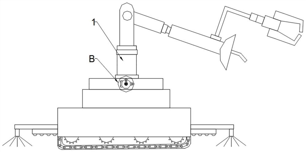
[0051] See figure 2 versus Figure 7 The nichoid body 9 is fixedly connected to the chassis 10, and the chassis 10 is distinguished from the sides of the clear hookami body 9, and the rotating gear 11 is connected, and the inner surface wall slides in the rotation gear 11, the slider 17 is fixedly connected. There is a light rod 18, and the light rod 18 is fixedly connected to the pressure plate 19, and the rotating gear 11 is fixedly connected to the handle, facilitating the operator rotating the gear 11, and engages the pressure plate 19 with the welding robot body 1.

[0052] Turn the handle, drive the rotating gear 11 to rotate, so that the slider 17 is moved along the slide on the inner wall of the rotation gear 11, since the slider 17 is fixed to the light rod 18, the light rod 18 will move along the bottom surface 10 The pressed plate 19 synchronous telescopic and welding robot body 1 is integrated, and the stability of the overall structure connection is improved, and the ...


PUM


Abstract

The invention discloses a 9-axis linkage welding robot with a C-shaped cantilever structure. The welding robot comprises a welding robot main body, a transmission pump and a smoke cleaning bin main body. During welding, the transmission pump sucks generated smoke into a drying pipe, large-particle substances are filtered out through a filter plate of a dust filtering bin, then the smoke enters anadsorption bin, part of the smoke is filtered out through activated carbon, then the smoke enters a reaction bin, absorption liquid is circularly sprayed out through a spraying pipe, and a gas-liquidreaction is achieved; when an electromagnetic valve is closed, gas in the reaction bin enters a drying bin through a circulating pipe and then is circularly purified and absorbed again; and when the electromagnetic valve is opened, the purified smoke is exhausted from a smoke exhaust pipe, so that the smoke generated by welding is treated, the smoke cleaning effect is better through circular treatment, and the use effect of a product is improved.

Description

Technical field [0001] The present invention relates to the field of welding techniques, and more particularly to a C-type cantilever structure 9-axis co-welding robot. Background technique [0002] Welding, also referred to as welding, and is a manufacturing process and technique of engaging metal or other thermoplastic materials such as plastic in a manner that heats, high temperature or high pressure. [0003] There are many energy sources of modern welding, including gas flame, arc, laser, electron beam, friction, and ultrasonic waves. In addition to being used in the factory, welding can also be carried out in a variety of environments, such as wild, underwater and space. No matter where, welding may bring hazards to the operator, so appropriate protective measures must be taken during welding. The damage to the human body may cause burns, electric shock, vision damage, inhalation of toxic gases, ultraviolet light excessive. [0004] At present, existing welding robots still...

Claims


Application Information

Patent Timeline
IPC IPC(8): B23K37/00B23K37/02B01D50/00B01D53/78
CPCB23K37/00B23K37/02B23K37/006B01D53/78B01D50/60
Inventor 张海瑞范宗敏
Owner 南京合信自动化有限公司
Why Eureka
Try Eureka