Eureka AIR delivers breakthrough ideas for toughest innovation challenges, trusted by R&D personnel around the world.

Injection mold with water blowing mechanism

An injection mold and water blowing technology, which is applied in the field of injection molds with a water blowing mechanism, can solve problems such as reducing the service life of the mold and corrosion of the mold, and achieve the effects of prolonging the service life, avoiding corrosion, and improving resource utilization

Inactive Publication Date: 2021-03-16
温州乾牧机械设备有限公司
View PDF0 Cites 0 Cited by
  • Summary
  • Abstract
  • Description
  • Claims
  • Application Information

AI Technical Summary

Problems solved by technology

[0003] In order to speed up the molding speed of the product, the existing injection mold usually cools the product after molding, but after cooling the product, some moisture will remain in the water channel on the mold, which will easily cause the inside of the mold to rust for a long time, reducing the The service life of the mold

Method used


Image

  • Injection mold with water blowing mechanism
  • Injection mold with water blowing mechanism
  • Injection mold with water blowing mechanism

Examples


Embodiment 1

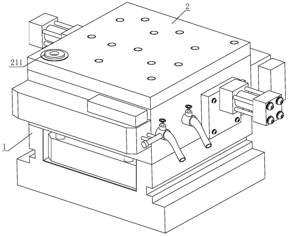
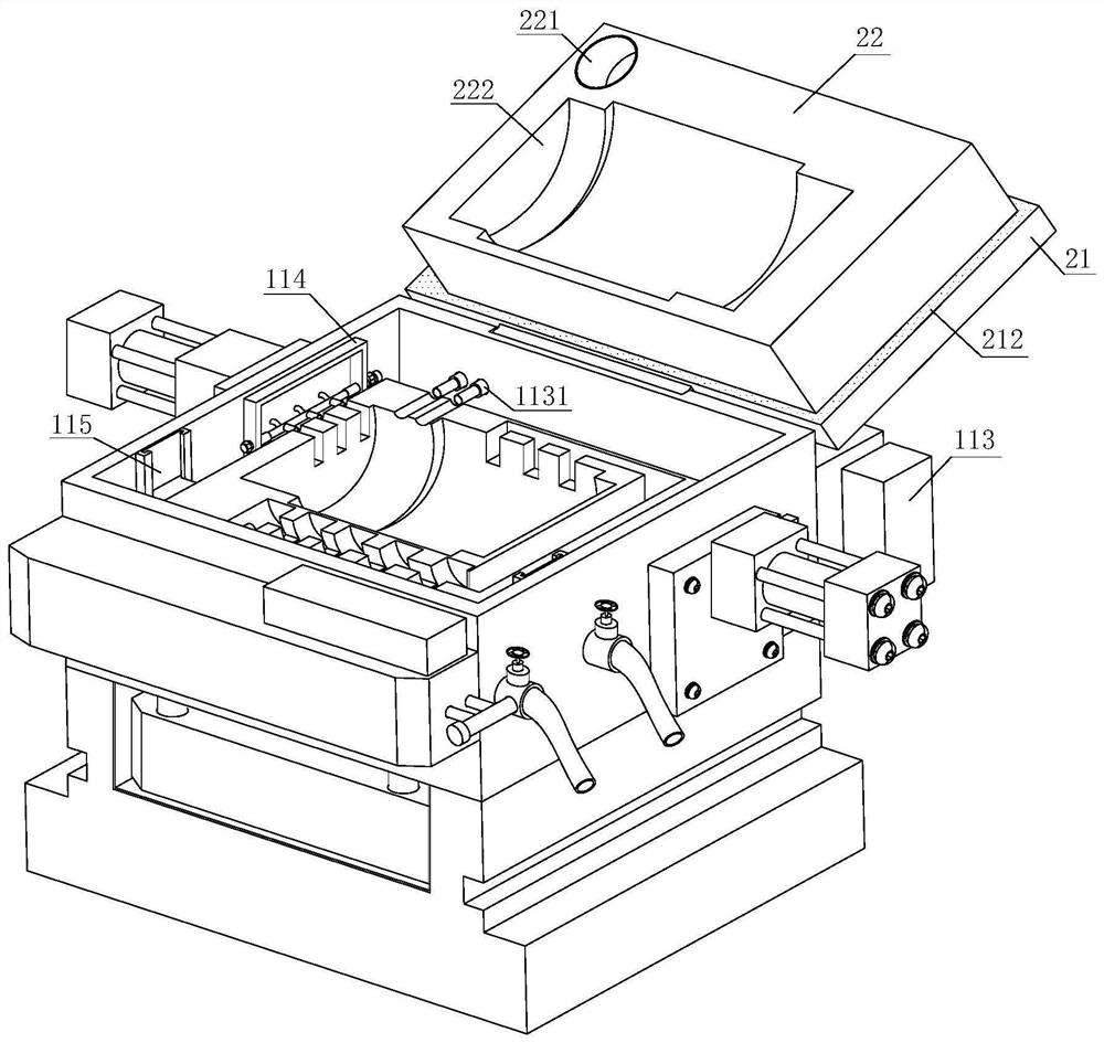
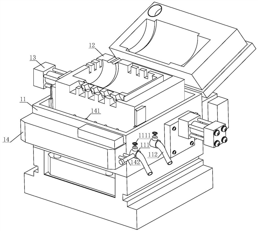
[0030] refer to figure 1 , figure 2 , image 3 , Figure 4 with Figure 7 , an injection mold with a water blowing mechanism, comprising an injection molding mechanism 1 and an upper cover mechanism 2, one side of the injection molding mechanism 1 is movably connected to the upper cover mechanism 2, and the injection molding mechanism 1 includes a housing 11, a lower mold Structure 12, air pump 13 and suction filter pump 14, the lower mold structure 12 is installed in the inner cavity of the housing 11, and an air pump 13 is arranged on one side of the outer wall of the housing 11, and the housing 11 is far away from the air pump 13 A cooling water inlet pipe 111 and a cooling water outlet pipe 112 are respectively installed on one side of the outer wall, the cooling water inlet pipe 111 and the cooling water outlet pipe 112 are connected to the inner cavity of the housing 11 and a valve 1111 is arranged at the upper end of the housing 11. The rear end is fixed with a slu...

Embodiment 2

[0032] refer to figure 2 , an injection mold with a water blowing mechanism, the upper cover mechanism 2 includes a cover body 21 and an upper mold body 22, the surface of the cover body 21 is provided with a cold air input port 211 near the corner, and the inner panel edge of the cover body 21 is provided There is a sealing strip 212, and the inner side of the cover body 21 is also fixed with an upper mold body 22; the surface of the upper mold body 22 is processed with a through hole 221 corresponding to the cold air input port 211, and the through hole 221 communicates with the cold air input port 211, and The surface of the upper mold body 22 is also processed with an upper molding cavity 222, which can use the cold air input port 211 to deliver cold air to the molding cavity during water-cooling molding, thereby further improving the molding rate.

Embodiment 3

[0034] refer to Figure 5-6 , an injection mold with a water blowing mechanism, the lower mold structure 12 includes a lower mold body 121 and a lower molding cavity 122, the surface of the lower mold body 121 is provided with a lower molding cavity 122, and the lower mold body 121 is close to the side of the blowing structure 114 The edge of the outer wall is processed with an air delivery groove 1211, one end of the air delivery groove 1211 is connected to the lower forming cavity 122 and the other end is connected to the air delivery pipe 1143; Groove 1221 and several sets of drainage grooves 1222, and the surface of the lower mold body 121 is also processed with a water groove 1212, one end of the water groove 1212 is connected to the drainage groove 1222; the side of the lower mold body 121 near the suction filter pump 14 is processed with several sets The water tank 1213 is connected by the water channel 12131 between adjacent water tanks 1213, and only one end of the wa...


PUM


Abstract

The invention discloses an injection mold with a water blowing mechanism. The injection mold comprises an injection molding mechanism and an upper cover mechanism, wherein one side of the injection molding mechanism is movably connected with the upper cover mechanism, the pressure in the mold is increased, and residual water spots in the mold are pressed into a suction filtration pump through a suction pipe to be recycled. According to the injection mold, one end of an air conveying groove is connected with a lower forming cavity, the other end of the air conveying groove communicates with anair conveying pipe, one end of a water flowing groove is connected with a water discharging groove, so that after the mold is used, air flow passes through an air inlet hose through an air pump, residual water spots in the lower forming cavity are blown through a blowing gun, the residual water spots is discharged into a water containing groove through a water flowing groove, finally, water spotsare pumped in through the suction filtration pump and discharged into a cooling water inlet pipe through a water discharging pipe, so that water flow can be conveniently input into the mold through the cooling water inlet pipe in the next injection molding process, the situation that water is remained in the molding cavities for a long time to cause internal corrosion is avoided, the service lifeof the molding cavities is prolonged, the resource utilization rate is increased, and environmental protection and energy saving are realized.

Description

technical field [0001] The invention relates to the technical field of injection molds, in particular to an injection mold with a water blowing mechanism. Background technique [0002] The mold generally includes two parts, the movable mold and the fixed mold (or punch and die), which can be separated or combined. Take out the parts when they are separated, and inject the blank into the mold cavity to form when they are closed. The mold is a precision tool with a complex shape and bears the bulging force of the billet. It has high requirements for structural strength, stiffness, surface hardness, surface roughness and machining accuracy. The development level of mold production is one of the important symbols of the level of mechanical manufacturing. Injection mold is a tool for producing plastic products; it is also a tool for giving plastic products complete structure and precise dimensions. Injection molding is a processing method used in the mass production of certain ...

Claims


Application Information

Patent Timeline
IPC IPC(8): B29C45/17B29C45/73
CPCB29C45/1753B29C45/7312B29C45/7337B29C2045/1754
Inventor 韩中军
Owner 温州乾牧机械设备有限公司
Why Eureka
Eureka Blog
Learn More