Intelligent loop line conveying line equipment

A conveyor line and equipment technology, applied in the field of conveyor lines, can solve the problems of high equipment cost, achieve the effects of reducing equipment cost, facilitating promotion, and reducing transportation distance

Pending Publication Date: 2021-03-16
广东都市物流科技有限公司
View PDF1 Cites 2 Cited by
  • Summary
  • Abstract
  • Description
  • Claims
  • Application Information

AI Technical Summary

Problems solved by technology

[0005] The purpose of the present invention is to provide an intelligent loop conveying line equipment, which has the advantage of reducing equipment cost and solves the problem of high equipment cost

Method used


Image

  • Intelligent loop line conveying line equipment
  • Intelligent loop line conveying line equipment
  • Intelligent loop line conveying line equipment

Examples


Embodiment 1

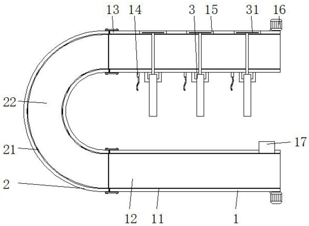
[0028] Embodiment 1: including the first conveying device body 1, the third conveying device body 2 and the support plate 4, the outer wall of the first conveying device body 1 is provided with a second conveying device body 13, the first conveying device body 1 and the second conveying device body The outer wall of one side of the conveying device body 13 is provided with a third conveying device body 2, and one side of the inner wall of the third conveying device body 2 is rotatably mounted with a circular array of turning rollers 21, and the outer wall of one side of the turning roller 21 is sleeved with a second conveying device body. Belt 22, turning roller 21 achieves the purpose of changing the moving direction of goods through the second conveyor belt 22;

[0029] The outer wall of one side of the third delivery device body 2 is equipped with connecting rods 23 distributed in a rectangular array, and the outer wall of one side of the connecting rods 23 is rotatably equi...

Embodiment 2

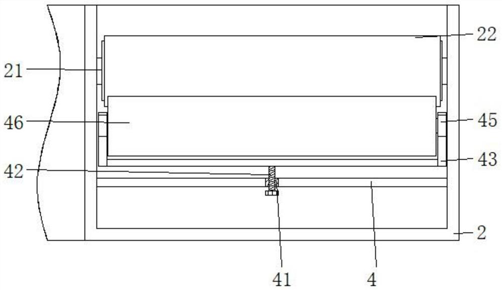
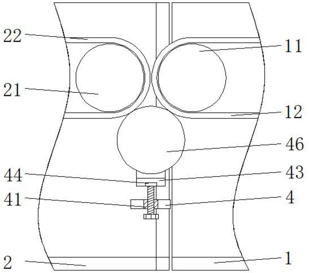
[0032]Embodiment 2: including the first conveying device body 1, the third conveying device body 2 and the support plate 4, the outer wall of the first conveying device body 1 is provided with a second conveying device body 13, the first conveying device body 1 and the second conveying device body The outer wall of one side of the delivery device body 13 is provided with the third delivery device body 2, and the outer walls of the first delivery device body 1 and the second delivery device body 13 are symmetrically installed with limit rods 18, and the lower end of the third delivery device body 2 inner wall is The support plate 4 is installed symmetrically on the side, and the inside of the support plate 4 is provided with a screw hole 41, and the screw hole 41 is internally threaded to be connected with a screw rod 42, and a first bearing 44 is installed on one side of the outer wall of the upper end of the screw rod 42, and the first conveying device body 1 and the second On...


PUM


Abstract

The invention discloses an intelligent loop line conveying line equipment comprising a first conveying device body, third conveying device bodies and supporting plates, and a second conveying device body is arranged on the outer wall of one side of the first conveying device body. The third conveying device bodies are arranged on the outer walls of one sides of the first conveying device body andthe second conveying device body correspondingly, limiting rods are symmetrically installed on the outer walls of the two sides of the first conveying device body and the second conveying device bodycorrespondingly, and the supporting plates are symmetrically installed on one sides of the lower ends of the inner walls of the third conveying device bodies. Screw holes are formed in the supportingplates, screw rods are in threaded connection with the interiors of the screw holes, and first bearings are installed on one sides of the outer walls of the upper ends of the screw rods. The third conveying device bodies, a transmission roller and a second bearing are arranged, thus the effect of conveniently driving a second conveying belt to rotate is achieved, the purpose of changing the movingdirection of goods is achieved, a power device is prevented from being additionally arranged, the equipment cost is reduced, and equipment popularization is facilitated.

Description

technical field [0001] The invention relates to the technical field of conveying lines, in particular to an intelligent loop conveying line equipment. Background technique [0002] The conveyor line is suitable for the transportation and handling of goods, replacing manual handling operations and reducing the labor force for handling. Automatic conveyors are widely used in the continuous delivery of light or medium-weight conveyed objects (such as packing boxes and turnover boxes) with relatively flat bottoms. They can also be used with The connection and use of other logistics machinery is an essential equipment for increasing productivity, reducing labor intensity and forming an automated production line in various industries. It has good compatibility and matching in the production process, and has simple structure, stability and reliability, low noise and low maintenance. Convenience and other advantages. [0003] After a large number of searches, it was found that the ...

Claims


Application Information

Patent Timeline
IPC IPC(8): B65G37/00B65G23/04B65G23/22B65G43/00B65G43/08B65G47/82
CPCB65G23/04B65G23/22B65G37/00B65G43/00B65G43/08B65G47/82B65G2203/04B65G2203/042
Inventor 林慧燕郑乐永
Owner 广东都市物流科技有限公司
Why Eureka
Try Eureka