
Fertilizer stirring device for compound fertilizer production

A technology of mixing device and compound fertilizer, which is applied to mixers with rotary mixing devices, accessories of mixers, mixers, etc., can solve the problems of reducing product quality, affecting the mixing effect of the device, and single mixing method.

Pending Publication Date: 2021-03-19
张春林
View PDF0 Cites 1 Cited by
  • Summary
  • Abstract
  • Description
  • Claims
  • Application Information

AI Technical Summary

Problems solved by technology

[0003] The traditional fertilizer stirring device generally only stirs the fertilizer solution through the stirring blades in one direction of rotation. During the process, the temperature will gradually decrease, causing some fertilizers to be prone to agglomeration, thereby reducing the product quality. Therefore, it is necessary to design a fertilizer mixing device for compound fertilizer production to solve the above problem.

Method used


Image

  • Fertilizer stirring device for compound fertilizer production
  • Fertilizer stirring device for compound fertilizer production
  • Fertilizer stirring device for compound fertilizer production

Examples


Embodiment 1

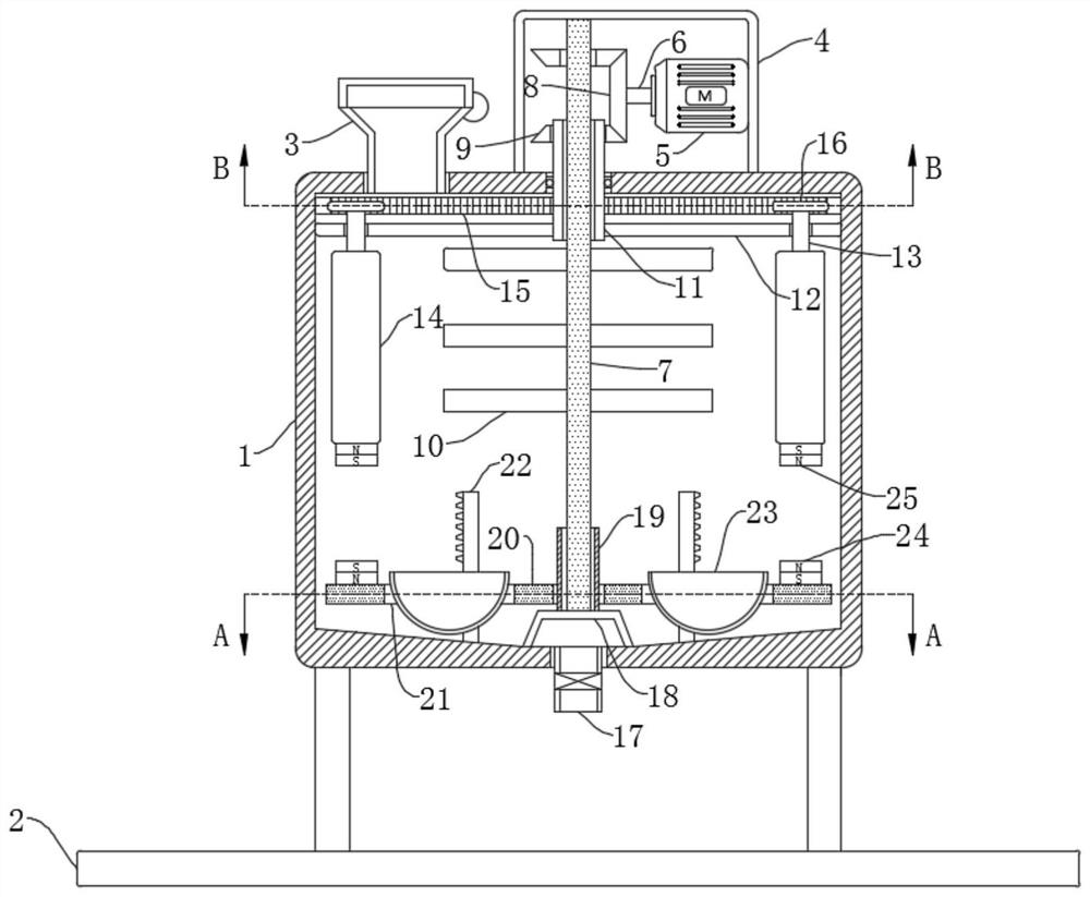
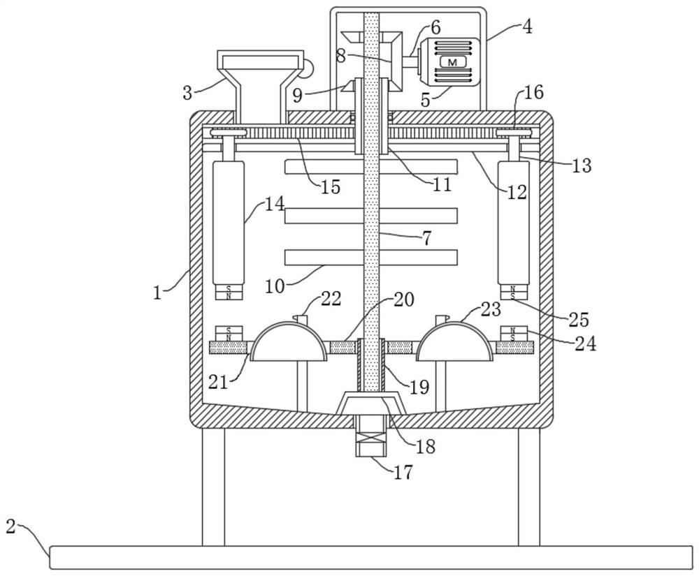
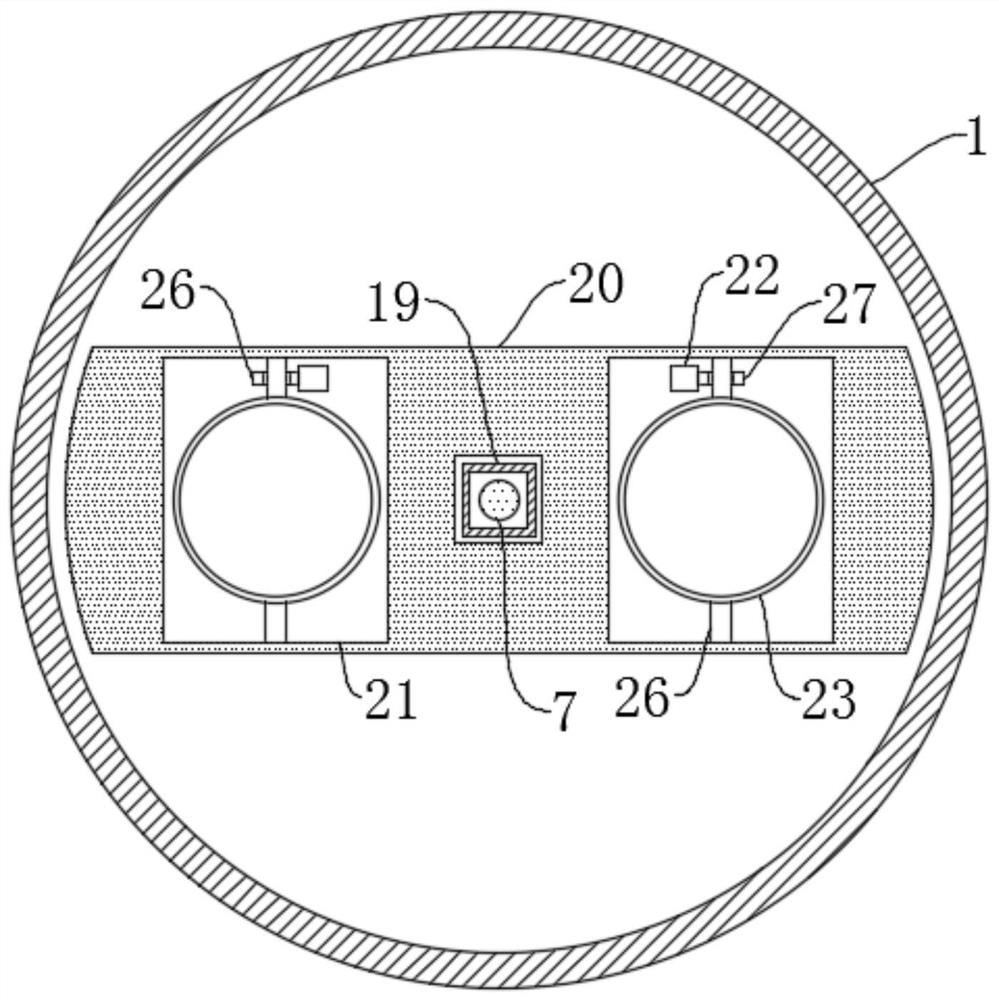
[0033] refer to Figure 1-4 , a fertilizer mixing device for compound fertilizer production, comprising a bottom plate 2, four support columns are fixedly connected to the upper wall of the bottom plate 2, a mixing box 1 is fixedly connected to the upper ends of the four support columns, and the upper wall of the mixing box 1 is connected with a feeding Pipe 3, feeding pipe 3 is in the shape of a funnel, the side wall of feeding pipe 3 is hinged and connected with a cover, which can prevent the fertilizer solution from splashing outside the mixing box 1 during the stirring process, and the lower wall of the mixing box 1 is connected with a discharge pipe 17. The discharge pipe 17 is provided with a solenoid valve.

[0034] The stirring box 1 is provided with a stirring mechanism, the stirring mechanism includes a fixed plate 18 fixedly connected to the inner bottom of the stirring box 1, the upper wall of the fixed plate 18 is rotatably connected with a rotating rod 7, and the...

Embodiment 2

[0046] refer to Figure 5 , different from Embodiment 1, the side wall of the mixing tank 1 is fixedly connected with a heat pipe 31, and the material of the heat pipe 31 is made of copper, which has a good heat conduction effect. The inner wall of the 28 is sealed and slidably connected with a piston 29 , the upper end of the piston 29 is fixedly connected with a moving rod 30 , and the upper end of the moving rod 30 is fixedly connected with the lower wall of the moving plate 20 .

[0047] The upper wall of the bottom plate 2 is fixedly connected with a heating box 32, and the heating box 32 is filled with heat-conducting oil, which is a kind of special oil product with good thermal stability for indirect heat transfer, and has the advantage of uniform heating. The inner top of 32 is fixedly connected with a heating rod 33, one end of the heat pipe 31 communicates with the fixed cylinder 28 through the water outlet pipe 35, and the end of the heat pipe 31 away from the fixed...


PUM


Abstract

The present invention discloses a fertilizer stirring device for compound fertilizer production. The fertilizer stirring device for compound fertilizer production comprises a bottom plate, four supporting columns are fixedly connected to the upper wall of the bottom plate, a stirring box is fixedly connected to the upper ends of the four supporting columns jointly, a feeding pipe is arranged on the upper wall of the stirring box in a communicating mode, a discharging pipe is arranged on the lower wall of the stirring box in a communicating mode, an electromagnetic valve is arranged on the discharging pipe, and a stirring mechanism is arranged on the stirring box. The device is reasonable in structural design, materials can be stirred in multiple directions, so that the materials move moreviolently in the stirring box, the stirring effect of the device on the materials is improved, a fertilizer solution located at the bottom can be turned up and down, and the fertilizer solution is uniformly mixed. Therefore, the problem of fertilizer caking caused by temperature reduction in the stirring process of the fertilizer solution is prevented.

Description

technical field [0001] The invention relates to the technical field of compound fertilizer production, in particular to a fertilizer stirring device for compound fertilizer production. Background technique [0002] Compound fertilizer refers to chemical fertilizer containing two or more nutrient elements. Compound fertilizer has the advantages of high nutrient content, less auxiliary components and good physical properties. It is very important for balanced fertilization, improving fertilizer utilization rate, and promoting high and stable yield of crops. In the production process of compound fertilizer, the mixing of fertilizer is one of the essential steps. [0003] The traditional fertilizer stirring device generally only stirs the fertilizer solution through the stirring blades in one direction of rotation. During the process, the temperature will gradually decrease, causing some fertilizers to easily agglomerate, thereby reducing the product quality. Therefore, it is n...

Claims


Application Information

Patent Timeline
IPC IPC(8): B01F7/30B01F7/18B01F15/06
CPCB01F27/192B01F27/95B01F27/90B01F2035/99B01F35/92B01F2101/32
Inventor 张春林
Owner 张春林
Learn More