Stamping device

A stamping device and punch technology, which is applied in the field of stamping devices, can solve problems such as bending deformation, affecting personal safety, and high probability of safety accidents, so as to prevent bending and deformation, ensure personal safety, and have a wide range of applications.

Pending Publication Date: 2021-03-19
XINCHANG HUAXIONG MACHINERY
View PDF0 Cites 0 Cited by
  • Summary
  • Abstract
  • Description
  • Claims
  • Application Information

AI Technical Summary

Problems solved by technology

[0002] In the stamping of thin-walled pipe parts, due to the thin thickness of the pipe and the hollow structure in the middle, its rigidity is poor, the stamping force should not be too large, it is easy to cause bending deformation, and the stroke should not be too large. It cannot be realized, and generally only laser cutting, plasma cutting and other methods can be used for processing. Due to the high price of these equipment, the processing cost of the pipe has doubled
However, in the traditional pressure punching machine, malfunctions often occur, and the probability of safety accidents is high. It is a dangerous operation and affects personal safety.

Method used


Image

  • Stamping device
  • Stamping device
  • Stamping device

Examples


Embodiment Construction

[0026] Specific embodiments of the present invention will be described in detail below in conjunction with the accompanying drawings.

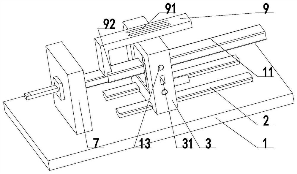
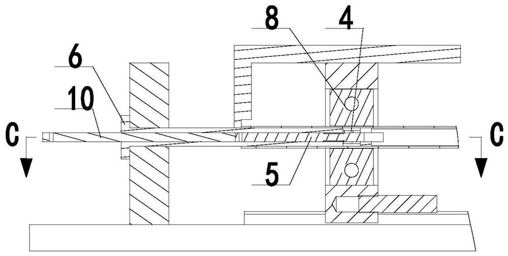
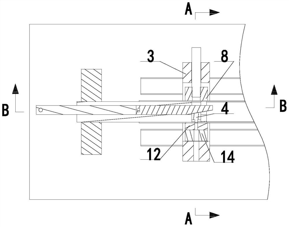
[0027] Such as Figure 1-11 As shown, the present invention is a stamping device.

[0028] The stamping device described in this embodiment includes a platen 1, the two ends of the platen 1 are respectively provided with a fixed block 7 and a guide rail 2, the shape of the section of the guide rail 2 is dovetail shape, and the guide rail 2 is provided with a slide Shift seat 3, slide seat 3 is the structure of intermediate cavity, connects power source on the slide seat 3, and described power source is hydraulic cylinder, because the connection mode of hydraulic cylinder is prior art, no longer expands here. The fixed block 7 is covered with a sheath 6, the sheath 6 is a hollow structure, the sheath 6 is a wear-resistant metal material, the workpiece 11 is sleeved on the sheath 6, and the outer dimension of the sheath 6 is slightly larger tha...


PUM


Abstract

The invention relates to the technical field of stamping, in particular to a stamping device, and solves the problem that during the stamping of parts such as thin-wall pipes, the rigidity is poor, and the stamping cannot be realized by a common stamping machine. The stamping device is characterized in that a fixed block and a guide rail are arranged on a bedplate; a sliding seat connected with apower source is arranged on the guide rail; a sheath sleeves the fixed block; a workpiece sleeves the sheath; a core rod and a loose core are sleeved with the sheath; the power source is connected tothe core rod; the sheath is provided with an opening; a stamping head sleeves the loose core and is clamped on the opening of the sheath and driven to carry out stamping through the linear motion of the loose core; a concave module is arranged on one side in a cavity of the sliding seat, and a movable block is connected to the other side in a sliding mode; the movable block is connected with the power source; and a positioning block is arranged above the sliding seat. According to the stamping device, a pipe fitting is arranged on the wear-resistant sheath, and the pipe wall is rigidly supported; the stamping head is driven to carry out stamping by the linear motion of the oblique loose core, so that the stamping action for the thin-wall pipe fitting is realized; and the stamping pressurecan be adjusted according to the inclination of the loose core and the size of a hydraulic cylinder, and the stamping device is suitable for various thin-wall pipe fittings.

Description

technical field [0001] The invention relates to the technical field of stamping, and more specifically relates to a stamping device. Background technique [0002] In the stamping of thin-walled pipe parts, due to the thin thickness of the pipe and the hollow structure in the middle, its rigidity is poor, the stamping force should not be too large, it is easy to cause bending deformation, and the stroke should not be too large. It cannot be realized, and generally only laser cutting, plasma cutting and other methods can be used for processing. Due to the high price of these equipment, the processing cost of the pipe has doubled. However, in the traditional pressure punching machine, misoperation often occurs, and the probability of safety accidents is high, which is a dangerous operation and affects personal safety. Contents of the invention [0003] The purpose of the present invention is to provide a stamping device with simple and reasonable structure, which is especial...

Claims


Application Information

Patent Timeline
IPC IPC(8): B21D22/02B21D37/10
CPCB21D22/025B21D37/10
Inventor 俞玉华石洪锋王潮泳陈少钦
Owner XINCHANG HUAXIONG MACHINERY
Why Eureka
Try Eureka