
Shockproof automobile stamping die

A technology for stamping dies and automobiles, applied in the field of stamping dies, can solve problems such as poor shockproof effect and affect service life, and achieve the effects of convenient replacement, improved friction, and improved convenience.

Inactive Publication Date: 2021-03-19
广州凯鑫智能装备科技有限公司
View PDF0 Cites 0 Cited by
  • Summary
  • Abstract
  • Description
  • Claims
  • Application Information

AI Technical Summary

Problems solved by technology

[0004] Based on the technical problems that the existing stamping dies have poor anti-shock effect and affect the service life during use, the present invention proposes a shock-proof automobile stamping die

Method used


Image

  • Shockproof automobile stamping die
  • Shockproof automobile stamping die
  • Shockproof automobile stamping die

Examples


Embodiment 1

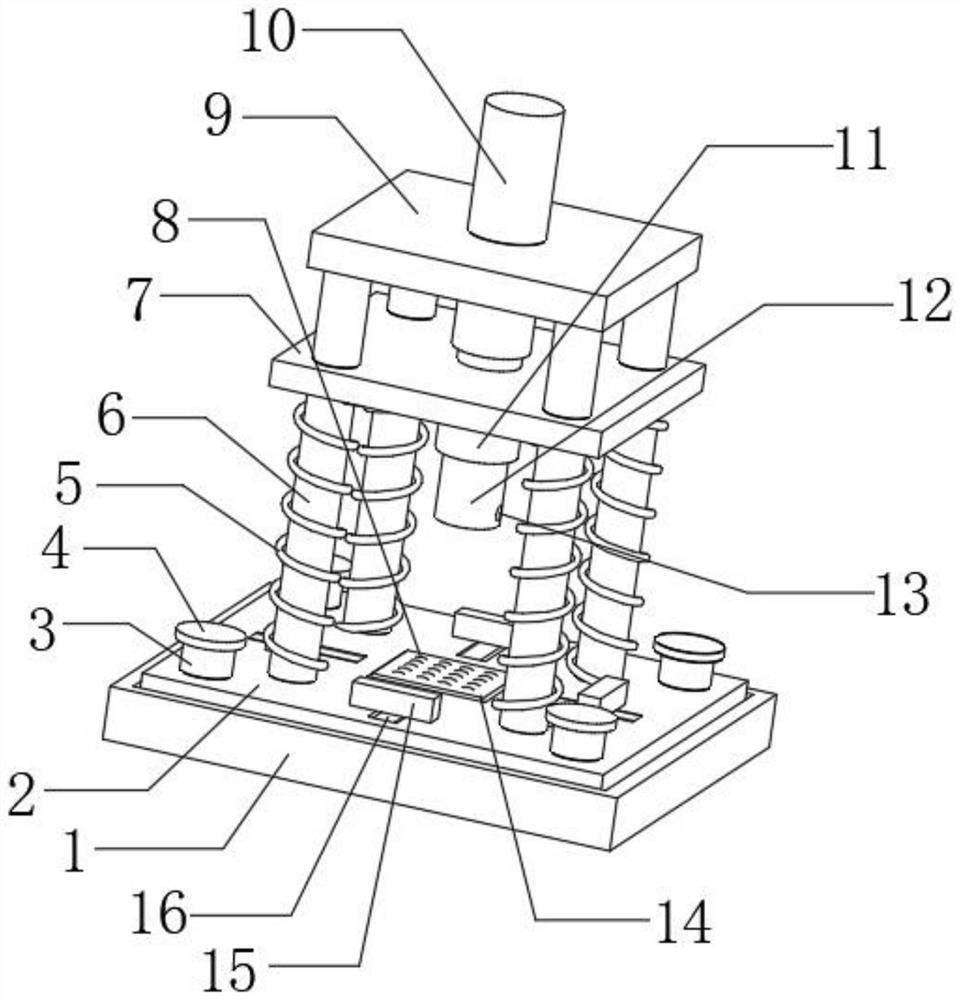
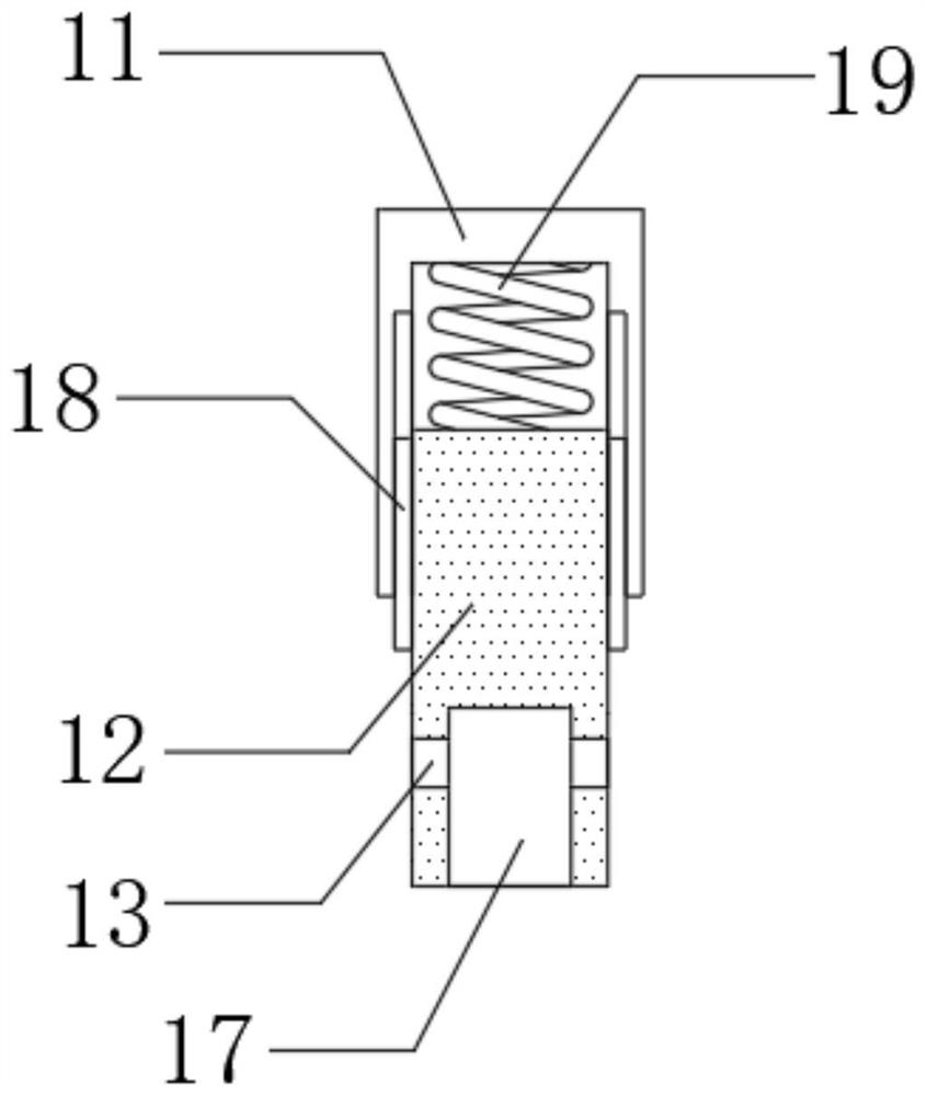
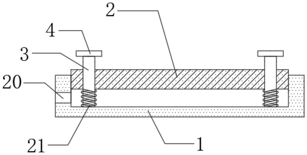
[0028] refer to Figure 1-3 , a shockproof automobile stamping die, comprising a support base 2, the outer walls of the top four corners of the support base 2 are connected with vertically arranged second limit rods 6 by bolts, and the top outer walls of the four second limit rods 6 are connected by bolts The same support top plate 9 is connected, and the top central outer wall of the support top plate 9 is provided with a first opening, the inner wall of the first opening is connected with a vertical hydraulic cylinder 10 by bolts, and the bottom outer wall of the hydraulic cylinder 10 is connected with a second opening by bolts. A support plate 7, and the top four corner outer walls of the first support plate 7 are provided with second openings, the inner walls of the four second openings are respectively slidingly connected with the circumferential outer walls of the four second limit rods, the first support plate 7 The central outer wall of the bottom is connected with a s...

Embodiment 2

[0038] refer to figure 1 , 2 And 4, a shockproof automobile stamping die, also includes the same annular water storage shell 23 installed on the bottom of the outer wall around the supporting groove plate 1 by bolts, and the exhaust hole 20 is replaced by a water guide pipe 22.

[0039] Working principle: When in use, set the exhaust hole as a water guide pipe, and set the same annular water storage shell on the outer wall around the supporting channel plate, so that clean water can be injected inside the supporting channel plate. During the stamping process, the water flow It is extruded through the water pipe, and then the water pressure realizes the buffering effect, and then achieves the shockproof effect.


PUM


Abstract

The invention belongs to the technical field of stamping dies, and particularly relates to a shockproof automobile stamping die. Aiming at at solving the problems that an existing stamping die is poorin shockproof effect and the service life is affected in the using process, the invention provides the following scheme that the shockproof automobile stamping die comprises a supporting base, wherein vertically-arranged second limiting rods are fixedly installed on the outer walls of the four corners of the top of the supporting base correspondingly; one same supporting top plate is fixedly installed on the outer walls of the tops of the four second limiting rods; and a first opening is formed in the outer wall of the center of the top of the supporting top plate. According to the shockproofautomobile stamping die provided by the invention, through the arrangement of a sleeve, an inserting rod, a threaded hole and a mounting groove, a stamping head needing to be used for stamping can befixedly mounted in the mounting groove through the threaded hole and a bolt, so that different stamping heads can be mounted and fixed through the arrangement, meanwhile, the stamping head can be replaced conveniently, and the use convenience of the device is improved; and the inserting rod is buffered through a second spring, so that effective stamping protection is achieved.

Description

technical field [0001] The invention relates to the technical field of stamping dies, in particular to a shockproof automobile stamping die. Background technique [0002] Stamping die is a special process equipment for processing materials (metal or non-metal) into parts (or semi-finished products) in cold stamping processing, called cold stamping die (commonly known as cold stamping die). Stamping is a pressure processing method that uses a mold installed on a press to apply pressure to the material at room temperature to cause separation or plastic deformation to obtain the required parts. [0003] In the processing of auto parts, some parts need to be stamped, and a stamping die will be used. The base of the existing stamping die is fixed on the ground or the table. During the stamping process, strong Instantaneous vibration will seriously affect the service life of the device, so it is necessary to design a shock-proof automotive stamping die to solve the above problems...

Claims


Application Information

Patent Timeline
IPC IPC(8): B21D37/10B21D55/00F16F15/08
CPCB21D37/10B21D55/00F16F15/085
Inventor 黄海荣
Owner 广州凯鑫智能装备科技有限公司
Learn More